CHARGING SYSTEM, Diagnostic DTC:P162B87
| DTC Code | DTC Name |
|---|---|
| P162B87 | Lost Communication with Battery Monitor Module Missing Message |
DESCRIPTION
The ECM communicates with the battery state sensor assembly via LIN communication. If a LIN communication error is detected, the ECM stores this DTC.
| DTC No. | Detection Item | DTC Detection Condition | Trouble Area | Warning Indicate | Memory | Note |
|---|---|---|---|---|---|---|
| P162B87 | Lost Communication with Battery Monitor Module Missing Message | Battery state sensor assembly or ECM communication stops for approximately 17 minutes or more with the engine switch on (IG). (1 trip detection logic) |
|
Charge warning light does not come on | DTC stored | SAE Code: P162B |
WIRING DIAGRAM
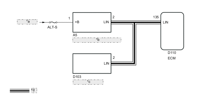
| *a | from Battery |
| *b | Battery State Sensor Assembly |
| *c | Generator Assembly |
| *d | LIN Communication Line |
CAUTION / NOTICE / HINT
Note
-
Inspect the fuses for circuits related to this system before performing the following procedure.
-
Make sure to perform the necessary procedures (adjustment, calibration, initialization, or registration) after parts related to the charging system have been removed/installed or replaced.
PROCEDURE
-
CHECK BATTERY STATE SENSOR ASSEMBLY INSTALLATION CONDITION
-
Check installation condition of the battery state sensor assembly.
Result Proceed to OK NG
NG 
INSTALL THE BATTERY STATE SENSOR ASSEMBLY CORRECTLY Click here
OK 
-
-
CHECK CHARGING SYSTEM
-
Check the charging system.
Result Proceed to OK NG
NG
REPAIR OR REPLACE CHARGING SYSTEM
OK
-
-
CHECK HARNESS AND CONNECTOR (ECM - BATTERY STATE SENSOR ASSEMBLY)
-
Disconnect the D110 ECM connector.
-
Disconnect the A5 battery state sensor assembly connector.
-
Disconnect the D103 generator assembly connector.
-
Measure the resistance according to the value(s) in the table below.
Standard Resistance Tester Connection Condition Specified Condition D110-135 (LIN) - A5-2 (LIN) Always Below 1 Ω D110-135 (LIN), A5-2 (LIN) or D103-2 (LIN) - Body ground Always 10 kΩ or higher Result Proceed to OK NG
NG
REPAIR OR REPLACE HARNESS OR CONNECTOR
OK
-
-
CHECK HARNESS AND CONNECTOR (POWER SOURCE CIRCUIT)
-
Check that the battery state sensor assembly connector is securely connected.
OK The connector is securely connected. -
Disconnect the A5 battery state sensor assembly connector.
-
Check the connector case and terminals for deformation or corrosion.
OK No deformation or corrosion. -
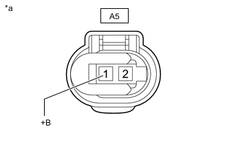
*a Front view of wire harness connector
(to Battery State Sensor Assembly)
Measure the voltage according to the value(s) in the table below.
Standard Voltage Tester Connection Condition Specified Condition A5-1 (+B) - Body ground Always 11 to 14 V Result Proceed to OK NG
NG
REPAIR OR REPLACE HARNESS OR CONNECTOR (BATTERY - BATTERY STATE SENSOR ASSEMBLY)
OK
-
-
CLEAR DTCS
-
Connect the GTS to the DLC3.
-
Turn the engine switch on (IG).
-
Turn the GTS on.
-
Enter the following menus: Powertrain / Engine / Trouble Codes.
-
Check for DTCs, and then write them down.
Powertrain > Engine > Trouble Codes -
Enter the following menus: Powertrain / Engine / Trouble Codes.
-
Clear the DTCs.
Powertrain > Engine > Clear DTCs -
Turn the engine switch off and wait 30 seconds.
Result Proceed to NEXT
NEXT
-
-
CHECK FOR DTCS
-
Connect the GTS to the DLC3.
-
Start the engine.
-
Allow the engine to idle for approximately 17 minutes or more.
-
Turn the GTS on.
-
Enter the following menus: Powertrain / Engine / Trouble Codes.
-
Check for DTCs.
Powertrain > Engine > Trouble CodesResult Result Proceed to Only DTC P162B87 is output. A DTC P161A87 and P162B87 are output. B DTCs are not output. C
A
REPLACE BATTERY STATE SENSOR ASSEMBLY Click here
B
REPLACE ECM Click here
C
CHECK FOR INTERMITTENT PROBLEMS Click here
-