CHARGING SYSTEM(w/ Battery Current Sensor) TERMINALS OF ECM
-
CHECK ECM
Tech Tips
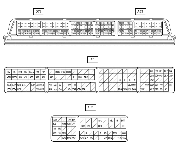
The standard normal voltage between each pair of ECM terminals is shown in the table below. The appropriate conditions for checking each pair of terminals are also indicated. The result of checks should be compared with the standard normal voltage for that pair of terminals, displayed in the Specified Condition column. The illustration above can be used as a reference to identify the ECM terminal locations.
Terminal No. (Symbol) Wiring Color Terminal Description Condition Specified Condition D73-111 (VCV1) - D73-110 (VV1-) G - P Power source of battery current sensor assembly Engine switch on (IG) 4.5 to 5.5 V A53-21 (RLO) - D73-49 (E1) Y - BR Generator 20 minutes elapsed after warming up, vehicle accelerating during charging control Pulse generation (Waveform 1) 20 minutes elapsed after warming up, vehicle decelerating during charging control Pulse generation (Waveform 2) D73-112 (ALT) - D73-49 (E1) L - BR Generator Engine switch on (IG) with the engine stopped 11 to 14 V D73-49 (E1) - Body ground BR - Body ground Ground Always Below 1 Ω A53-1 (BATT) - D73-49 (E1) V - BR Battery (for measuring battery voltage and for ECM memory) Always 11 to 14 V A53-20 (INH) - D73-49 (E1) R - BR Wiper switch signal Engine switch on (IG), wiper switch HI position 11 to 14 V A53-40 (IB) - D73-110 (VV1-) GR - P Battery current sensor (built into battery current sensor assembly) Engine switch on (IG), Battery temperature sensor ambient temperature -30 to 90°C (-22 to 194°F) 0.2 to 4.8 V D73-95 (THB) - D73-110 (VV1-) LG - P Battery temperature sensor (built into battery current sensor assembly) Engine switch on (IG) 0.2 to 4.8 V -
OSCILLOSCOPE WAVEFORMS
Tech Tips
Oscilloscope waveform samples are provided here for informational purposes. Noise and fluttering waveforms have been omitted.
-
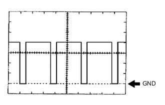
Waveform 1
Item Content Terminal A53-21 (RLO) - D73-49 (E1) Equipment Setting 2 V/DIV., 50 ms/DIV. Condition 20 minutes elapsed after warming up, vehicle accelerating during charging control Tech Tips
The waveform does not appear constantly because the duty ratio varies depending on the electrical load and battery state.
-
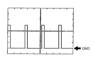
Waveform 2
Item Content Terminal A53-21 (RLO) - D73-49 (E1) Equipment Setting 2 V/DIV., 50 ms/DIV. Condition 20 minutes elapsed after warming up, vehicle decelerating during charging control Tech Tips
The waveform does not appear constantly because the duty ratio varies depending on the electrical load and battery state.
-