REAR TRAILING ARM REMOVAL
CAUTION / NOTICE / HINT
The necessary procedures (adjustment, calibration, initialization, or registration) that must be performed after parts are removed, installed, or replaced during the rear trailing arm assembly removal/installation are shown below.
| Replacement Part or Procedure | Necessary Procedures | Effects/Inoperative when not Performed | Link |
|---|---|---|---|
| Work that changes the vehicle height such as replacement or removal/installation of the rear height control sensor sub-assembly or replacement of suspension components | Initialize headlight ECU sub-assembly LH | Headlight leveling function | |
| Rear wheel alignment adjustment |
|
|
Tech Tips
-
Use the same procedure for the RH side and LH side.
-
The following procedure is for the LH side.
PROCEDURE
-
REMOVE REAR WHEEL
-
REMOVE LOWER NO. 2 CONTROL ARM COVER
-
SEPARATE SKID CONTROL SENSOR WIRE
-
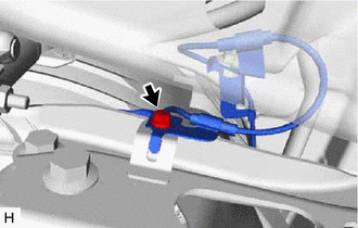
Remove the bolt and separate the skid control sensor wire from the rear trailing arm assembly.
-
-
REMOVE REAR TRAILING ARM ASSEMBLY
-
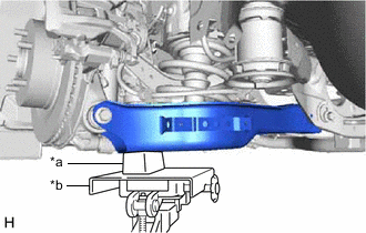
*a Wooden Block *b Transmission Jack Using a transmission jack and a wooden block, support the rear No. 2 suspension arm assembly.
Note
-
When jacking up the rear No. 2 suspension arm assembly, be sure to jack it up slowly.
-
Make sure to perform this operation with the vehicle kept as low as possible.
-
-
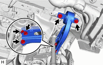
Remove the 5 bolts and rear trailing arm assembly.
-
Slowly lower the rear No. 2 suspension arm assembly.
-