REAR LOWER ARM REMOVAL
CAUTION / NOTICE / HINT
The necessary procedures (adjustment, calibration, initialization, or registration) that must be performed after parts are removed, installed, or replaced during the rear suspension arm assembly removal/installation are shown below.
| Replacement Part or Procedure | Necessary Procedures | Effects/Inoperative when not Performed | Link |
|---|---|---|---|
| Work that changes the vehicle height such as replacement or removal/installation of the rear height control sensor sub-assembly or replacement of suspension components | Initialize headlight light control ECU sub-assembly LH | Headlight leveling function | |
| Rear wheel alignment adjustment |
|
|
Tech Tips
-
Use the same procedure for the RH side and LH side.
-
The following procedure is for the LH side.
PROCEDURE
-
REMOVE REAR WHEEL
-
REMOVE LOWER NO. 1 CONTROL ARM COVER
-
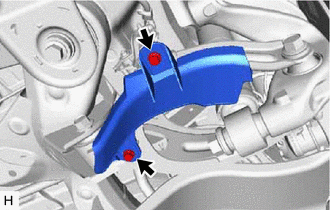
Remove the 2 bolts and lower No. 1 control arm cover from the rear No. 1 suspension arm assembly.
-
-
REMOVE LOWER NO. 2 CONTROL ARM COVER
-
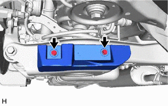
Remove the 2 bolts and lower No. 2 control arm cover from the rear No. 2 suspension arm assembly.
-
-
SEPARATE REAR HEIGHT CONTROL SENSOR SUB-ASSEMBLY
-
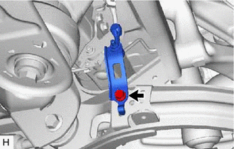
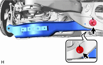
Remove the bolt and separate the rear height control sensor sub-assembly from the rear No. 1 suspension arm assembly.
-
-
REMOVE REAR NO. 1 SUSPENSION ARM ASSEMBLY
-
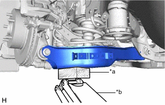
*a Wooden Block *b Jack Using a jack and a wooden block, support the rear No. 2 suspension arm assembly.
Note
-
When jacking up the rear No. 2 suspension arm assembly, be sure to jack it up slowly.
-
Make sure to perform this operation with the vehicle kept as low as possible.
-
-
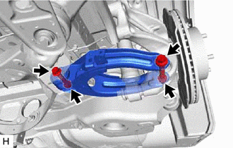
Remove the 2 bolts, 2 nuts and rear No. 1 suspension arm assembly from the rear axle carrier sub-assembly and rear suspension member sub-assembly.
Note
Because the nut has its own stopper, do not turn the nut. Loosen the bolt with the nut secured.
-
-
SEPARATE REAR FLEXIBLE HOSE
-
SEPARATE STABILIZER LINK SUB-ASSEMBLY
-
REMOVE REAR COIL SPRING
-
REMOVE REAR LOWER COIL SPRING INSULATOR
-
REMOVE REAR NO. 2 SUSPENSION ARM ASSEMBLY
-
Remove the bolt, rear No. 2 suspension toe adjust plate, rear suspension toe adjust cam sub-assembly and rear No. 2 suspension arm assembly.
Note
Hold the rear No. 2 suspension toe adjust plate while rotating the bolt.
-
-
REMOVE NO. 6 FLEXIBLE HOSE BRACKET
-
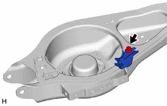
Remove the bolt and No. 6 flexible hose bracket from the rear No. 2 suspension arm assembly.
-
-
REMOVE NO. 5 FLEXIBLE HOSE BRACKET
-
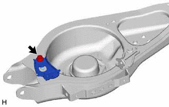
Remove the bolt and No. 5 flexible hose bracket from the rear No. 2 suspension arm assembly.
-