REAR COIL SPRING INSTALLATION
CAUTION / NOTICE / HINT
Tech Tips
-
Use the same procedure for the RH side and LH side.
-
The following procedure is for the LH side.
PROCEDURE
-
INSTALL REAR UPPER COIL SPRING INSULATOR
-
Install the rear upper coil spring insulator to the vehicle.
-
-
INSTALL REAR LOWER COIL SPRING INSULATOR
-
for LH Side:
-
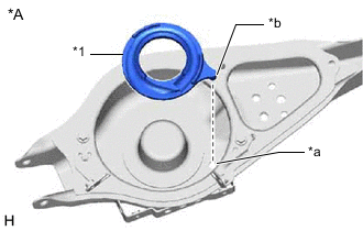
*A for LH Side *1 Rear Lower Coil Spring Insulator LH *a Guide Hole *b Protrusion Install the rear lower coil spring insulator LH to the rear No. 2 suspension arm assembly LH.
Note
Securely insert the protrusion of the rear lower coil spring insulator LH into the guide hole of the rear No. 2 suspension arm assembly LH.
-
-
for RH Side:
-
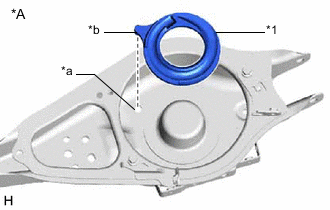
*A for RH Side *1 Rear Lower Coil Spring Insulator RH *a Guide Hole *b Protrusion Install the rear lower coil spring insulator RH to the rear No. 2 suspension arm assembly RH.
Note
Securely insert the protrusion of the rear lower coil spring insulator RH into the guide hole of the rear No. 2 suspension arm assembly RH.
-
-
-
INSTALL REAR COIL SPRING
-
for LH Side:
-
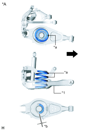
*A for LH Side *1 Rear No. 2 Suspension Arm Assembly LH *a Identification Mark *b 20 mm or less 
Inner Side of the Vehicle Set the rear coil spring LH to the rear No. 2 suspension arm assembly LH.
Note
-
Install the rear coil spring LH with its identification marks facing inner side of the vehicle.
-
Make sure that the rear coil spring LH is not installed upside down by confirming that the identification marks on the rear coil spring LH are not within the rear No. 2 suspension arm assembly LH.
-
Install the rear lower coil spring insulator LH so that the dimension between the stopper and lower end of the rear coil spring LH is 20 mm (0.787 in.) or less.
-
Confirm that the lower end of the rear coil spring LH is facing the rear of the vehicle.
-
-
-
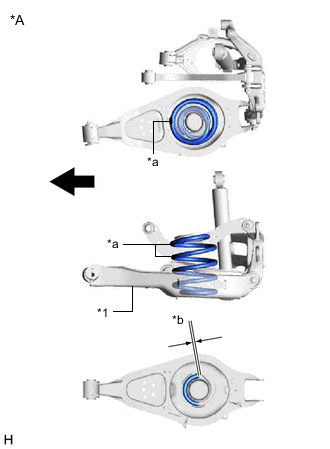
*A for RH Side *1 Rear No. 2 Suspension Arm Assembly RH *a Identification Mark *b 20 mm or less Inner Side of the Vehicle for RH Side:
Note
-
Install the rear coil spring RH with its identification marks facing inner side of the vehicle.
-
Make sure that the rear coil spring RH is not installed upside down by confirming that the identification marks on the rear coil spring RH are not within the rear No. 2 suspension arm assembly RH.
-
Install the rear lower coil spring insulator RH so that the dimension between the stopper and lower end of the rear coil spring RH is 20 mm (0.787 in.) or less.
-
Confirm that the lower end of the rear coil spring RH is facing the front of the vehicle.
-
-
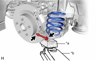
*a Wooden Block *b Jack Using a jack and wooden block, slowly jack up the rear No. 2 suspension arm assembly and then temporarily install the rear No. 2 suspension arm assembly to the rear axle carrier sub-assembly with the bolt and nut.
CAUTION:
Do not jack up the rear No. 2 suspension arm assembly too high as the vehicle may fall.
Note
-
Because the nut has its own stopper, do not turn the nut. Tighten the bolt with the nut secured.
-
When jacking up the rear No. 2 suspension arm assembly, be sure to jack it up slowly.
-
Make sure to perform this operation with the vehicle kept as low as possible.
-
Insert the bolt with the threaded end facing the front of the vehicle.
-
-
-
INSTALL STABILIZER LINK SUB-ASSEMBLY
-
Install the stabilizer link sub-assembly to the rear No. 2 suspension arm assembly with the 2 nuts.
- Torque:
- 50 N*m { 510 kgf*cm, 37 ft.*lbf }
-
-
INSTALL REAR FLEXIBLE HOSE
-
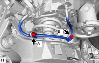
Install the rear flexible hose to the No. 5 flexible hose bracket and No. 6 flexible hose bracket with the 2 bolts.
- Torque:
- Bolt (A)
- 18.8 N*m { 192 kgf*cm, 14 ft.*lbf }
- Bolt (B)
- 17.8 N*m { 182 kgf*cm, 13 ft.*lbf }
-
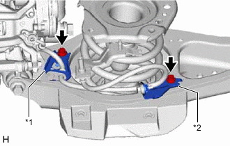
*1 No. 5 Flexible Hose Bracket *2 No. 6 Flexible Hose Bracket Tighten the bolts of the No. 5 flexible hose bracket and No. 6 flexible hose bracket shown in the illustration.
- Torque:
- 17.8 N*m { 182 kgf*cm, 13 ft.*lbf }
Tech Tips
The bolts of the flexible hose brackets may become loose after removing and installing the rear flexible hose.
-
-
STABILIZE SUSPENSION
-
INSTALL REAR NO. 2 SUSPENSION ARM ASSEMBLY
-
Install the rear No. 2 suspension arm assembly (rear axle carrier sub-assembly side) with the bolt.
-
-
INSTALL LOWER NO. 2 CONTROL ARM COVER
-
INSTALL REAR WHEEL
-
INSTALL REAR NO. 2 SUSPENSION ARM ASSEMBLY
-
Install the rear No. 2 suspension arm assembly (rear suspension member sub-assembly side) with the bolt.
-
-
INSPECT AND ADJUST REAR WHEEL ALIGNMENT
-
PERFORM INITIALIZATION
-
Initialization of the headlight ECU sub-assembly LH.
-