FRONT SUSPENSION MEMBER INSTALLATION

PROCEDURE
-
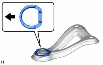
INSTALL FRONT SUSPENSION MEMBER BODY MOUNTING REAR CUSHION (for LH Side)
-
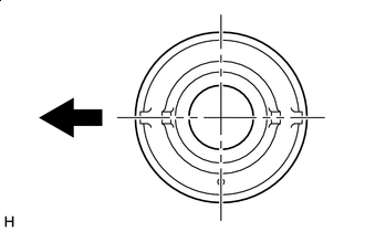

Front of the Vehicle Align a new front suspension member body mounting rear cushion as shown in the illustration and set it to the front suspension crossmember sub-assembly.
-
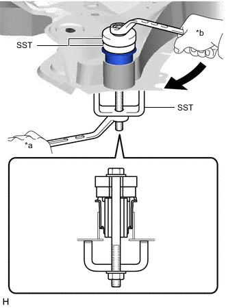
*a Hold *b Turn Using SST, press the front suspension member body mounting rear cushion into the front suspension crossmember sub-assembly.
- SST
- 09710-28031 ( 09711-02010, 90101-12177, 90170-12110, 94612-11200 )
- 09950-60010 ( 09951-00600, 09951-00610 )
Tech Tips
Apply grease to the threads of SST.
-
-
INSTALL FRONT SUSPENSION MEMBER BODY MOUNTING REAR CUSHION (for RH Side)
Tech Tips
Perform the same procedure as for the LH side.
-
INSTALL FRONT SUSPENSION MEMBER BODY MOUNTING FRONT CUSHION (for LH Side)
-
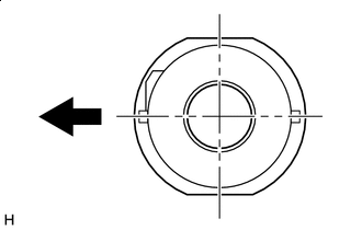
Front of the Vehicle Align a new front suspension member body mounting front cushion as shown in the illustration and set it to the front suspension crossmember sub-assembly.
-
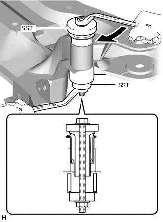
*a Hold *b Turn Using SST, press the front suspension member body mounting front cushion into the front suspension crossmember sub-assembly.
- SST
- 09710-28031 ( 90101-12177, 90170-12110, 94612-11200 )
- 09710-30021 ( 09710-03141 )
- 09950-60010 ( 09951-00440, 09951-00600 )
Tech Tips
Apply grease to the threads of SST.
-
-
INSTALL FRONT SUSPENSION MEMBER BODY MOUNTING FRONT CUSHION (for RH Side)
Tech Tips
Perform the same procedure as for the LH side.
-
INSTALL FRONT SUSPENSION MEMBER BODY MOUNTING REAR STOPPER (for LH Side)
-
Front of the Vehicle Install a new front suspension member body mounting rear stopper to the front suspension member brace sub-assembly LH.
-
-
INSTALL FRONT SUSPENSION MEMBER BODY MOUNTING REAR STOPPER (for RH Side)
Tech Tips
Perform the same procedure as for the LH side.
-
INSTALL FRONT SUSPENSION MEMBER BODY MOUNTING FRONT STOPPER
-
Install 2 new front suspension member body mounting front stoppers to the front suspension crossmember sub-assembly.
-
-
INSTALL FRONT LOWER SUSPENSION MEMBER MOUNTING CUSHION
-
Install 4 new front lower suspension member mounting cushions to the front suspension crossmember sub-assembly.
-
-
INSTALL FRONT LOWER SUSPENSION MEMBER MOUNTING SPACER
-
Install 4 new front lower suspension member mounting spacers to the front suspension crossmember sub-assembly.
-
-
INSTALL STEERING LINK ASSEMBLY
-
INSTALL FRONT STABILIZER BAR
-
INSTALL FRONT SUSPENSION MEMBER FRONT BRACE LH
-
INSTALL FRONT SUSPENSION MEMBER FRONT BRACE RH
Tech Tips
Perform the same procedure as for the LH side.
-
TEMPORARILY TIGHTEN FRONT LOWER NO. 1 SUSPENSION ARM SUB-ASSEMBLY LH (for 2AR-FE)
-
TEMPORARILY TIGHTEN FRONT LOWER NO. 1 SUSPENSION ARM SUB-ASSEMBLY RH (for 2AR-FE)
Tech Tips
Perform the same procedure as for the LH side.
-
INSTALL FRONT LOWER NO. 1 SUSPENSION ARM SUB-ASSEMBLY LH (for 2GR-FE)
-
TEMPORARILY TIGHTEN FRONT LOWER NO. 1 SUSPENSION ARM SUB-ASSEMBLY RH (for 2GR-FE)
-
INSTALL FRONT SUSPENSION CROSSMEMBER SUB-ASSEMBLY
-
Slowly jack up the front suspension crossmember sub-assembly with an engine lifter using 4 attachments or equivalent tools.
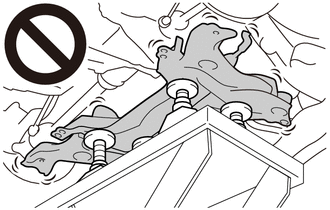
CAUTION:
-
The front suspension crossmember sub-assembly is a very heavy component. Make sure that it is supported securely.
-
If the front suspension crossmember sub-assembly is not securely supported, it may drop, resulting in serious injury.
Note
Use attachments to keep the front suspension crossmember sub-assembly level.
-
-
Uniformly tighten the 2 bolts while alternately inserting SST into the left and right side reference holes in the front suspension crossmember sub-assembly.
- SST
- 09670-00020
- Torque:
- 137 N*m { 1397 kgf*cm, 101 ft.*lbf }
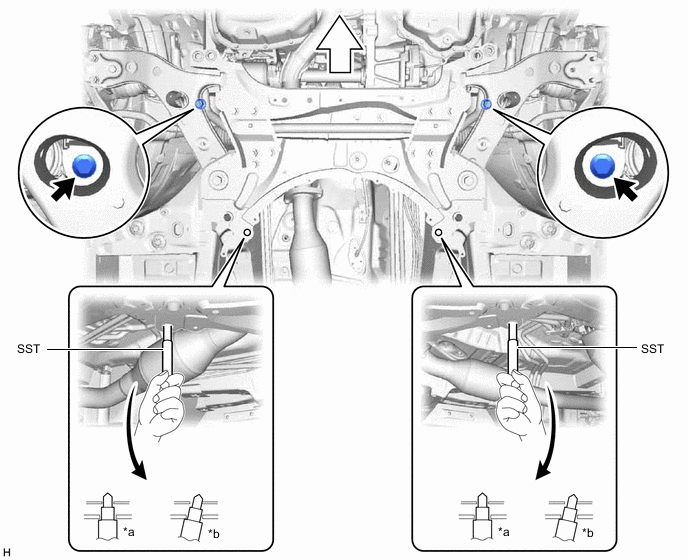
*a OK *b NG 
Front of the Vehicle - - -
Lower the engine lifter.
-
Connect the rear engine mounting insulator to the front suspension crossmember sub-assembly with the 2 bolts and 2 nuts.
- Torque:
- 95 N*m { 969 kgf*cm, 70 ft.*lbf }
-
-
INSTALL FRONT CROSS MEMBER SUB-ASSEMBLY
-
Install the front cross member sub-assembly to the vehicle body with the 4 bolts.
- Torque:
- 96 N*m { 979 kgf*cm, 71 ft.*lbf }
-
for 2AR-FE
-
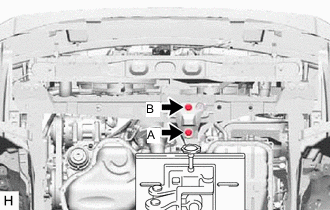
Connect the front engine mounting insulator to the front cross member sub-assembly with the 2 bolts.
- Torque:
- 95 N*m { 969 kgf*cm, 70 ft.*lbf }
Note
Temporarily tighten the bolt (A) and then fully tighten the 2 bolts in the order of (B) and (A).
-
-
for 2GR-FE
-
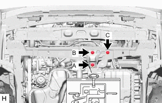
Connect the front engine mounting insulator to the front cross member sub-assembly with the 3 bolts.
- Torque:
- 95 N*m { 969 kgf*cm, 70 ft.*lbf }
Note
Temporarily tighten the bolt (A) and then fully tighten the 3 bolts in the order of (B), (C) and (A).
-
-
-
INSTALL FRONT SUSPENSION MEMBER BRACE SUB-ASSEMBLY LH
-
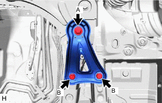
Install the front suspension member brace sub-assembly LH to the front suspension crossmember sub-assembly and vehicle body with the 2 bolts (B) and bolt (A).
- Torque:
- Bolt (A)
- 137 N*m { 1397 kgf*cm, 101 ft.*lbf }
- Bolt (B)
- 81 N*m { 826 kgf*cm, 60 ft.*lbf }
-
-
INSTALL FRONT SUSPENSION MEMBER BRACE SUB-ASSEMBLY RH
Tech Tips
Perform the same procedure as for the LH side.
-
INSTALL FRONT SUSPENSION MEMBER REINFORCEMENT LH
-
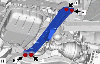
Install the front suspension member reinforcement LH to the front cross member sub-assembly and front suspension crossmember sub-assembly with the 4 bolts.
- Torque:
- 96 N*m { 979 kgf*cm, 71 ft.*lbf }
Note
Temporarily tighten the bolts (A) and (B), and then fully tighten the 4 bolts in the order of (C), (B), (D) and (A).
-
-
INSTALL FRONT SUSPENSION MEMBER REINFORCEMENT RH
Tech Tips
Perform the same procedure as for the LH side.
-
CONNECT FRONT LOWER NO. 1 SUSPENSION ARM SUB-ASSEMBLY LH
-
CONNECT FRONT LOWER NO. 1 SUSPENSION ARM SUB-ASSEMBLY RH
Tech Tips
Perform the same procedure as for the LH side.
-
CONNECT TIE ROD END SUB-ASSEMBLY LH
-
CONNECT TIE ROD END SUB-ASSEMBLY RH
Tech Tips
Perform the same procedure as for the LH side.
-
CONNECT FRONT STABILIZER LINK ASSEMBLY LH
-
Connect the front stabilizer link assembly LH to the front stabilizer bar with the nut.
- Torque:
- 74 N*m { 755 kgf*cm, 55 ft.*lbf }
Note
Do not damage the boot of the ball joint.
Tech Tips
If the ball joint turns together with the nut, use a 6 mm hexagon socket wrench to hold the stud bolt.
-
-
CONNECT FRONT STABILIZER LINK ASSEMBLY RH
Tech Tips
Perform the same procedure as for the LH side.
-
CONNECT NO. 1 STEERING COLUMN HOLE COVER SUB-ASSEMBLY
-
CONNECT NO. 2 STEERING INTERMEDIATE SHAFT ASSEMBLY
-
INSTALL COLUMN HOLE COVER SILENCER SHEET
-
INSTALL REAR ENGINE UNDER COVER LH
for 2AR-FE: Click here
for 2GR-FE: Click here
-
INSTALL REAR ENGINE UNDER COVER RH
for 2AR-FE: Click here
for 2GR-FE: Click here
-
INSTALL NO. 2 ENGINE UNDER COVER (for Front Side)
for 2AR-FE: Click here
for 2GR-FE: Click here
-
INSTALL NO. 2 ENGINE UNDER COVER (for Rear Side)
-
Install the No. 2 engine under cover to the front suspension crossmember sub-assembly with the 4 clips.
-
-
INSTALL NO. 1 ENGINE UNDER COVER
for 2AR-FE: Click here
for 2GR-FE: Click here
-
INSTALL FRONT LOWER BUMPER ABSORBER
-
Install the front lower bumper absorber to the vehicle body with the 8 bolts and 4 clips.
-
-
INSTALL FRONT BUMPER COVER
for ALPHARD: Click here
for VELLFIRE: Click here
-
INSTALL FRONT WHEELS
-
STABILIZE SUSPENSION
-
Lower the vehicle.
-
Press down on the vehicle several times to stabilize the suspension.
-
-
FULLY TIGHTEN FRONT LOWER NO. 1 SUSPENSION ARM SUB-ASSEMBLY LH (for 2AR-FE)
-
FULLY TIGHTEN FRONT LOWER NO. 1 SUSPENSION ARM SUB-ASSEMBLY RH (for 2AR-FE)
Tech Tips
Perform the same procedure as for the LH side.
-
FULLY TIGHTEN FRONT LOWER NO. 1 SUSPENSION ARM SUB-ASSEMBLY LH (for 2GR-FE)
-
FULLY TIGHTEN FRONT LOWER NO. 1 SUSPENSION ARM SUB-ASSEMBLY RH (for 2GR-FE)
-
INSPECT AND ADJUST FRONT WHEEL ALIGNMENT
-
PERFORM INITIALIZATION
-
Initialization of the headlight light control ECU sub-assembly LH.
-
-
ADJUST FOG LIGHT AIMING
for LED Type: Click here
for Bulb Type: Click here
-
ADJUST FRONT TELEVISION CAMERA ASSEMBLY (w/ Panoramic View Monitor System)