FRONT STABILIZER BAR REMOVAL
CAUTION / NOTICE / HINT
The necessary procedures (adjustment, calibration, initialization, or registration) that must be performed after parts are removed, installed, or replaced during the front stabilizer bar removal/installation are shown below.
| Replacement Part or Procedure | Necessary Procedures | Effects/Inoperative when not Performed | Link |
|---|---|---|---|
| Front wheel alignment adjustment |
|
|
|
| Work that changes the vehicle height such as replacement or removal/installation of the rear height control sensor sub-assembly LH or replacement of suspension components | Initialize headlight ECU sub-assembly LH | Headlight leveling function | |
| Removal/installtaion of the radiator grille | Television camera view adjustment | Panoramic view monitor system |
PROCEDURE
-
REMOVE FRONT SUSPENSION CROSSMEMBER SUB-ASSEMBLY
-
REMOVE FRONT STABILIZER LINK ASSEMBLY LH
-
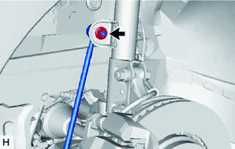
Remove the nut and front stabilizer link assembly LH from the front shock absorber assembly LH.
Note
Do not damage the boot of the ball joint.
Tech Tips
If the ball joint turns together with the nut, use a 6 mm hexagon socket wrench to hold the stud bolt.
-
-
REMOVE FRONT STABILIZER LINK ASSEMBLY RH
Tech Tips
Perform the same procedure as for the LH side.
-
REMOVE FRONT LOWER NO. 1 SUSPENSION ARM SUB-ASSEMBLY RH
-
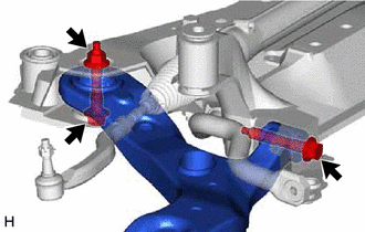
Remove the 2 bolts, nut and front lower No. 1 suspension arm sub-assembly RH from the front suspension crossmember sub-assembly.
Note
Because the nut has its own stopper, do not turn the nut. Loosen the bolt with the nut secured.
-
-
REMOVE FRONT SUSPENSION MEMBER FRONT BRACE LH
-
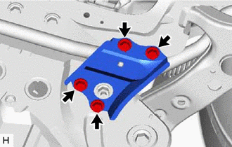
Remove the 4 bolts and front suspension member front brace LH from the front suspension crossmember sub-assembly.
-
-
REMOVE FRONT SUSPENSION MEMBER FRONT BRACE RH
Tech Tips
Perform the same procedure as for the LH side.
-
REMOVE FRONT STABILIZER BAR
-
Remove the front stabilizer bar with 2 front stabilizer bar bushings from the front suspension crossmember sub-assembly.
-
-
REMOVE FRONT STABILIZER BAR BUSHING LH
-
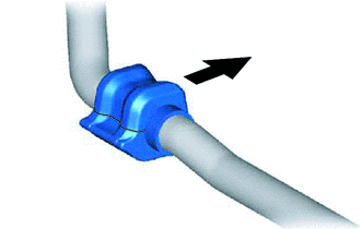
Remove the front stabilizer bar bushing LH from the front stabilizer bar.
-
-
REMOVE FRONT STABILIZER BAR BUSHING RH
Tech Tips
Perform the same procedure as for the LH side.