REAR AXLE CARRIER INSTALLATION
CAUTION / NOTICE / HINT
Tech Tips
-
Use the same procedure for the RH side and LH side.
-
The following procedure is for the LH side.
PROCEDURE
-
TEMPORARILY INSTALL REAR AXLE CARRIER SUB-ASSEMBLY
-
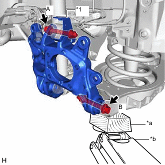
*1 Parking Brake Wire Bracket *a Wooden Block *b Jack Temporarily install the rear axle carrier sub-assembly to the rear upper control arm assembly with the parking brake wire bracket, bolt (A) and nut.
Note
-
Insert the bolt with the threaded end facing the rear of the vehicle.
-
Because the nut has its own stopper, do not turn the nut. Tighten the bolt with the nut secured.
-
-
Temporarily install the rear axle carrier sub-assembly to the rear No. 2 suspension arm assembly with the bolt (B) and nut.
Note
-
Insert the bolt with the threaded end facing the front of the vehicle.
-
Because the nut has its own stopper, do not turn the nut. Tighten the bolt with the nut secured.
-
-
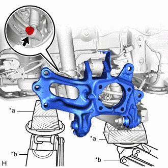
*a Wooden Block *b Jack Using a jack and wooden block, jack up the rear axle carrier sub-assembly (front side).
Note
When jacking up the rear axle carrier sub-assembly, be sure to jack it up slowly.
-
Temporarily install the rear axle carrier sub-assembly to the rear shock absorber assembly with the bolt.
-
-
INSTALL REAR TRAILING ARM ASSEMBLY
-
TEMPORARILY INSTALL REAR NO. 1 SUSPENSION ARM ASSEMBLY
-
INSTALL REAR AXLE HUB AND BEARING ASSEMBLY
-
INSTALL SKID CONTROL SENSOR WIRE
-
Install the skid control sensor wire to the rear trailing arm assembly and rear axle carrier sub-assembly with the 2 bolts.
- Torque:
- 8.5 N*m { 87 kgf*cm, 75 in.*lbf }
-
Connect the skid control sensor wire connector.
-
-
INSTALL REAR DISC
-
INSTALL REAR DISC BRAKE CALIPER ASSEMBLY
-
STABILIZE SUSPENSION
-
INSTALL REAR NO. 2 SUSPENSION ARM ASSEMBLY
-
Install the rear No. 2 suspension arm assembly (rear axle carrier sub-assembly side) with the bolt.
-
-
INSTALL REAR NO. 1 SUSPENSION ARM ASSEMBLY
-
INSTALL REAR UPPER CONTROL ARM ASSEMBLY
-
INSTALL REAR SHOCK ABSORBER ASSEMBLY
-
Install the rear shock absorber assembly with the bolt (lower side).
- Torque:
- 160 N*m { 1632 kgf*cm, 118 ft.*lbf }
-
-
INSTALL REAR HEIGHT CONTROL SENSOR SUB-ASSEMBLY
-
INSTALL LOWER NO. 1 CONTROL ARM COVER
-
INSTALL LOWER NO. 2 CONTROL ARM COVER
-
INSTALL REAR WHEEL
-
INSTALL REAR NO. 2 SUSPENSION ARM ASSEMBLY
-
Install the rear No. 2 suspension arm assembly (rear suspension member sub-assembly side) with the bolt.
-
-
INSPECT AND ADJUST REAR WHEEL ALIGNMENT
-
CHECK FOR SPEED SENSOR SIGNAL
-
PERFORM INITIALIZATION
-
Initialization of the headlight light control ECU sub-assembly LH.
-
-
INSPECT AUTOMATIC LIGHT CONTROL SYSTEM
-
INSPECT HEADLIGHT AIMING
for ALPHARD: Click here
for VELLFIRE: Click here