OIL COOLER INSTALLATION
PROCEDURE
-
INSTALL OIL COOLER
-
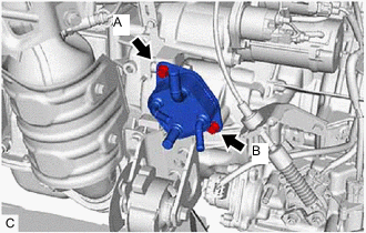
Install the oil cooler to the transaxle case with the 2 bolts.
- Torque:
- 11.5 N*m { 117 kgf*cm, 8 ft.*lbf }
Note
Tightening order: Temporarily tighten bolt (A) → Fully tighten bolt (B) → Fully tighten bolt (A)
-
Connect the inlet No. 1 oil cooler hose to the oil cooler and slide the clip to secure it.
Note
Align the paint mark on the inlet No. 1 oil cooler hose with the one on the oil cooler.
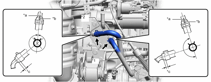
*1 Inlet No. 1 Oil Cooler Hose *2 Outlet No. 1 Oil Cooler Hose *a Black Mark *b Yellow Mark *c 2 to 7 mm (0.079 to 0.276 in.) - - -
Connect the outlet No. 1 oil cooler hose to the oil cooler and slide the clip to secure it.
Note
Align the paint mark on the outlet No. 1 oil cooler hose with the one on the oil cooler.
-
-
CONNECT NO. 2 WATER BY-PASS HOSE
-
Connect the No. 2 water by-pass hose to the oil cooler and slide the 2 clips to secure them.
Note
-
Align each paint mark on the No. 2 water by-pass hose with each one on the oil cooler.
-
Fully insert the No. 2 water by-pass hose to the 2nd rib on each oil cooler pipe.
-
-
-
INSTALL BATTERY CARRIER SUPPORT
-
INSTALL BATTERY CARRIER
-
INSTALL BATTERY
-
INSTALL CENTER NO. 1 COWL TOP VENTILATOR LOUVER
-
CONNECT CABLE TO NEGATIVE BATTERY TERMINAL
Note
When disconnecting the cable, some systems need to be initialized after the cable is reconnected.
-
ADD ENGINE COOLANT
-
INSPECT FOR COOLANT LEAK
-
ADD CONTINUOUSLY VARIABLE TRANSAXLE FLUID
-
INSPECT FOR FLUID LEAK
-
INSTALL REAR ENGINE UNDER COVER LH