AUTOMATIC TRANSAXLE UNIT DISASSEMBLY

CAUTION / NOTICE / HINT
The necessary procedures (adjustment, calibration, initialization, or registration) that must be performed after parts are removed, installed, or replaced during the transmission valve body assembly removal/installation are shown below.
| Replacement Part or Procedure | Necessary Procedures | Effects/Inoperative when not Performed | Link |
|---|---|---|---|
| Replacement of valve body assembly | Perform the following procedures in the order shown:
|
|
Click here for Initialization Click here for Registration |
PROCEDURE
-
REMOVE BREATHER PLUG HOSE
-
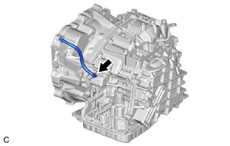
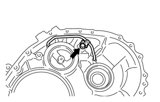
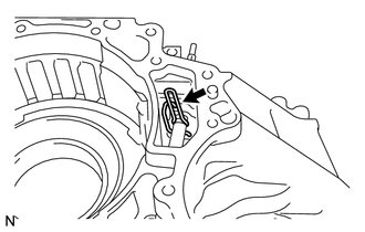
Using a screwdriver with its tip wrapped with protective tape, remove the breather plug hose from the transaxle case sub-assembly.
-
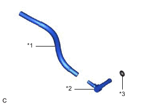
*1 Breather Plug Hose *2 No. 2 Breather Plug (ATM) *3 O-ring Using a screwdriver with its tip wrapped with protective tape, remove the No. 2 breather plug (ATM) from the breather plug hose.
-
Using a screwdriver with its tip wrapped with protective tape, remove the O-ring from the No. 2 breather plug (ATM).
-
-
REMOVE PARK/NEUTRAL POSITION SWITCH ASSEMBLY
-
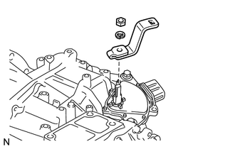
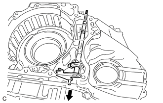
Remove the nut, washer and transmission control shaft lever from the manual valve lever shaft sub-assembly.
-
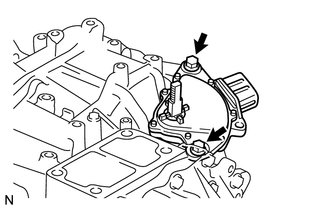
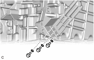
Remove the 2 bolts and park/neutral position switch assembly from the manual valve lever shaft sub-assembly.
Note
Before removing the park/neutral position switch assembly, remove any dirt or rust on the installation portion of the manual valve lever shaft sub-assembly. Be sure to remove the park/neutral position switch assembly straight along the manual valve lever shaft sub-assembly while being careful not to deform the plate spring that supports the manual valve lever shaft sub-assembly. If the plate spring is deformed, the park/neutral position switch assembly cannot be reinstalled correctly.
-
-
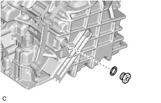
REMOVE OIL COOLER OUTLET ELBOW
-
Remove the oil cooler outlet elbow from the transaxle case sub-assembly.
-
Remove the O-ring from the oil cooler outlet elbow.
-
-
REMOVE OIL COOLER INLET ELBOW
-
Remove the oil cooler inlet elbow from the transaxle case sub-assembly.
-
Remove the O-ring from the oil cooler inlet elbow.
-
-
REMOVE NO. 1 TRANSAXLE CASE PLUG
-
Remove the 3 No. 1 transaxle case plugs from the transaxle case sub-assembly.
-
Using a screwdriver with its tip wrapped with protective tape, remove the 3 O-rings from the 3 No. 1 transaxle case plugs.
-
-
REMOVE NO. 2 TRANSAXLE CASE PLUG
-
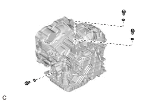
Using a 6 mm hexagon socket wrench, remove the 3 No. 2 transaxle case plugs from the transaxle housing.
-
Remove the gasket from each of the 3 No. 2 transaxle case plugs.
-
-
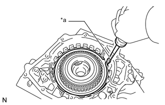
SUPPORT AUTOMATIC TRANSAXLE ASSEMBLY
-
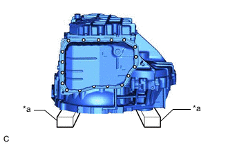
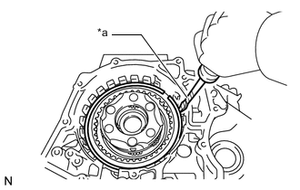
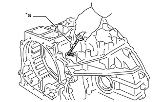
*a Wooden Block Support the automatic transaxle assembly with wooden blocks.
-
-
REMOVE AUTOMATIC TRANSAXLE OIL PAN SUB-ASSEMBLY
-
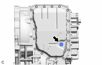
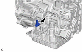
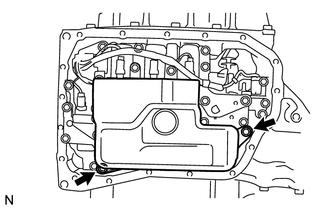
Using a 6 mm hexagon socket wrench, remove the overflow plug from the automatic transaxle oil pan sub-assembly.
-
Remove the gasket from the overflow plug.
-

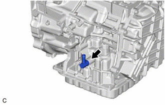
Using a 6 mm hexagon socket wrench, remove the No. 1 transmission oil filler tube from the automatic transaxle oil pan sub-assembly.
-
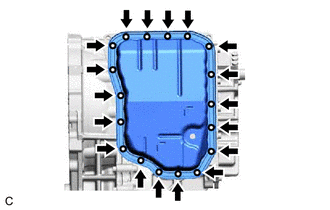
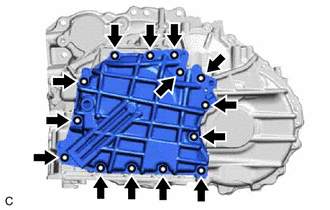
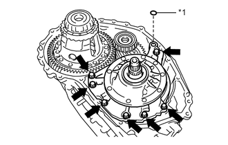
Remove the 18 bolts, automatic transaxle oil pan sub-assembly and automatic transaxle oil pan gasket from the transaxle case sub-assembly.
Note
Some fluid will remain in the automatic transaxle oil pan sub-assembly. Remove all of the bolts and carefully remove the automatic transaxle oil pan sub-assembly.
-
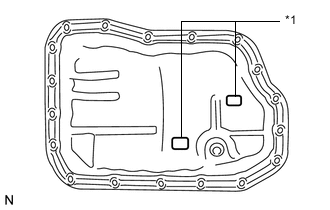
*1 Transmission Oil Cleaner Magnet Remove the 2 transmission oil cleaner magnets from the automatic transaxle oil pan sub-assembly.
-
-
INSPECT TRANSMISSION OIL CLEANER MAGNET
-
REMOVE VALVE BODY OIL STRAINER ASSEMBLY
-
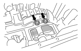
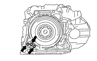
Remove the 2 bolts and valve body oil strainer assembly from the transmission valve body assembly.
-
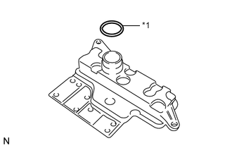
*1 O-ring Remove the O-ring from the valve body oil strainer assembly.
-
-
REMOVE TRANSMISSION VALVE BODY ASSEMBLY
-
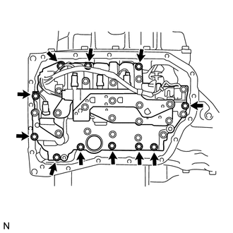
Remove the 11 bolts and transmission valve body assembly from transaxle case sub-assembly.
Note
When removing the transmission valve body assembly, be careful not to allow the transmission revolution sensor and transaxle case sub-assembly to interfere with each other.
-
-
REMOVE TRANSAXLE CASE GASKET
-
Remove the 2 transaxle case gaskets from the transaxle case sub-assembly.
-
-
INSPECT INPUT SHAFT SUB-ASSEMBLY END PLAY
-
REMOVE REAR TRANSAXLE COVER SUB-ASSEMBLY
-
Remove the refill plug from the rear transaxle cover sub-assembly.
-
Remove the gasket from the refill plug.
-
Remove the 3 No. 1 automatic transaxle case plugs from the rear transaxle cover sub-assembly.
-
Using a screwdriver with its tip wrapped with protective tape, remove the 3 O-rings from the 3 No. 1 automatic transaxle case plugs.
-
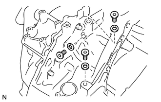
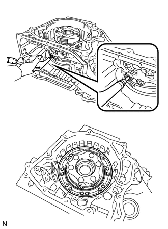
Remove the 14 bolts from the rear transaxle cover sub-assembly.
-
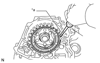
Using a brass bar and a hammer, tap on the circumference of the rear transaxle cover sub-assembly to remove the rear transaxle cover sub-assembly from the transaxle case sub-assembly.
-
Using a screwdriver with its tip wrapped with protective tape, remove the 3 O-rings from the transaxle case sub-assembly.
-
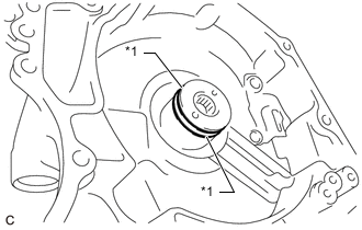
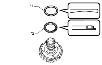
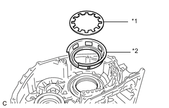
*1 Thrust Needle Roller Bearing *2 Thrust Needle Roller Race Remove the thrust needle roller bearing and thrust needle roller race from the rear transaxle cover sub-assembly.
-
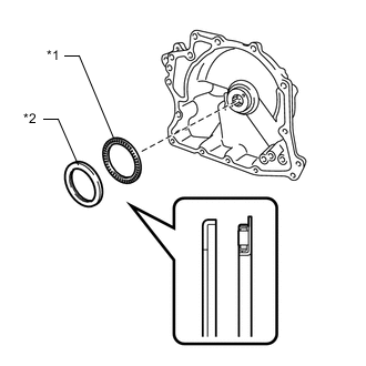
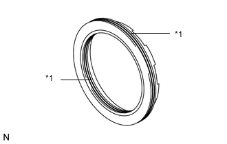
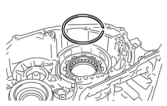
*1 Oil Seal Ring Using a screwdriver with its tip wrapped with protective tape, remove the 2 oil seal rings from the rear transaxle cover sub-assembly.
-
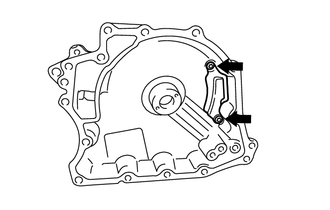
Using a T30 "TORX" socket wrench, remove the 2 "TORX" screws and rear transaxle cover plate from the rear transaxle cover sub-assembly.
-
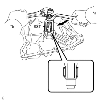
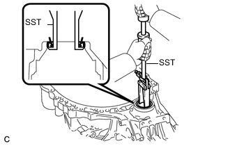
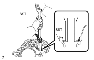
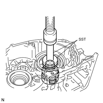
*a Turn *b Hold Using SST, remove the needle roller bearing from the rear transaxle cover sub-assembly.
- SST
- 09319-60020
-
-
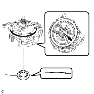
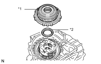
REMOVE DIRECT MULTIPLE DISC CLUTCH ASSEMBLY
-
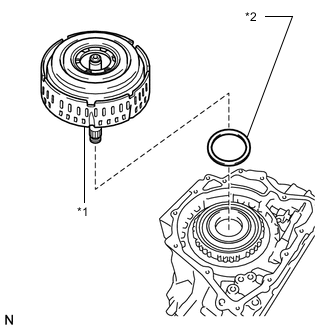
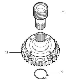
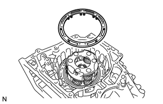
*1 Direct Multiple Disc Clutch Assembly *2 Thrust Needle Roller Bearing Remove the direct multiple disc clutch assembly from the transaxle case sub-assembly.
-
Remove the thrust needle roller bearing from the direct multiple disc clutch assembly.
-
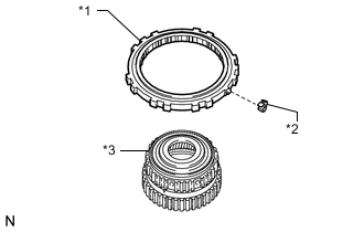
*1 Intermediate Shaft Oil Seal *2 O-ring Using a screwdriver with its tip wrapped with protective tape, remove the intermediate shaft oil seal from the direct multiple disc clutch assembly.
-
Using a screwdriver with its tip wrapped with protective tape, remove the O-ring from the direct multiple disc clutch assembly.
-
-
REMOVE DIRECT MULTIPLE DISC CLUTCH SNAP RING
-
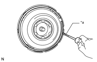
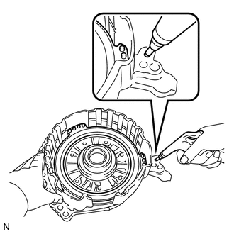
*a Protective Tape Using a screwdriver with its tip wrapped with protective tape, remove the direct multiple disc clutch snap ring from the direct multiple disc clutch assembly.
-
Remove the No. 2 direct clutch piston from the direct multiple disc clutch assembly.
-
-
REMOVE NO. 2 CLUTCH DISC
-
*1 No. 2 Clutch Plate *2 No. 2 Clutch Disc *3 No. 2 Clutch Flange Remove the No. 2 clutch flange, 3 No. 2 clutch discs and 3 No. 2 clutch plates from the direct multiple disc clutch assembly.
-
-
INSPECT NO. 2 CLUTCH DISC
-
REMOVE REAR PLANETARY SUN GEAR ASSEMBLY
-
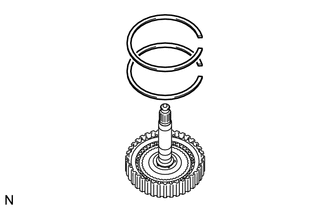
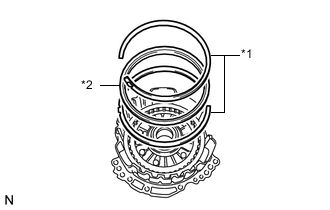
Using a snap ring expander, remove the snap ring from the direct multiple disc clutch assembly.
-
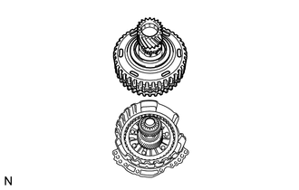
*1 Rear Planetary Sun Gear Assembly Remove the rear planetary sun gear assembly from the direct multiple disc clutch assembly.
-
*1 Thrust Needle Roller Bearing *2 Thrust Needle Roller Race Remove the thrust needle roller bearing and thrust needle roller race from the direct multiple disc clutch assembly.
-
-
INSPECT REAR PLANETARY SUN GEAR ASSEMBLY
-
REMOVE NO. 1 CLUTCH DISC
-
Using 2 screwdrivers, remove the 2 snap rings from the direct multiple disc clutch assembly.
-
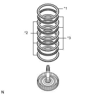
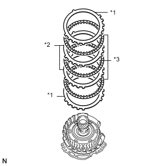
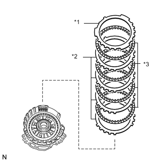
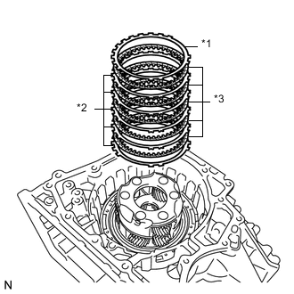
*1 No. 1 Clutch Flange *2 No. 1 Clutch Plate *3 No. 1 Clutch Disc Remove the No. 1 clutch flange, 4 No. 1 clutch discs and 4 No. 1 clutch plates from the direct multiple disc clutch assembly.
-
-
INSPECT NO. 1 CLUTCH DISC
-
REMOVE TRANSAXLE HOUSING
-
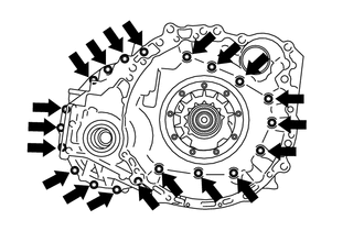
Remove the 20 bolts from the transaxle housing.
-
Using a brass bar and a hammer, tap on the circumference of the transaxle housing to remove the transaxle housing from the transaxle case sub-assembly.
-
-
REMOVE COUNTER DRIVEN GEAR FRONT TAPERED ROLLER BEARING (OUTER RACE)
-
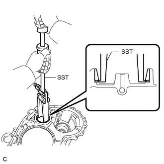
Using SST, remove the counter driven gear front tapered roller bearing (outer race) and shim from the transaxle housing.
- SST
- 09308-00010
-
-
REMOVE FRONT DRIVE SHAFT OIL SEAL RH
-
Using SST, remove the front drive shaft oil seal RH from the transaxle housing.
- SST
- 09308-00010
-
-
REMOVE FRONT DIFFERENTIAL CASE FRONT TAPERED ROLLER BEARING (OUTER RACE)
-
Using SST, remove the front differential case front tapered roller bearing (outer race) and shim from the transaxle housing.
- SST
- 09308-00010
-
-
REMOVE DIFFERENTIAL GEAR LUBE APPLY TUBE
-
Remove the bolt, clamp and differential gear lube apply tube from the transaxle housing.
-
-
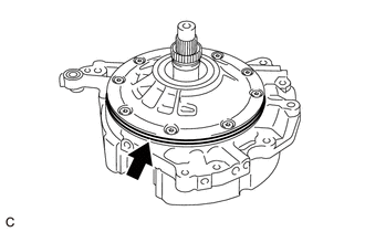
REMOVE FRONT OIL PUMP ASSEMBLY
-
*1 Gasket Remove the 7 bolts and front oil pump assembly from the transaxle case sub-assembly.
-
Remove the gasket from the front oil pump assembly.
-
*1 Thrust Needle Roller Race Remove the thrust needle roller race from the underdrive planetary gear assembly.
-
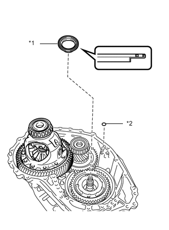
*1 Thrust Needle Roller Bearing *2 O-ring Remove the thrust needle roller bearing from the counter drive gear nut.
-
Remove the O-ring from the transaxle case sub-assembly.
-
-
REMOVE FRONT OIL PUMP BODY O-RING
-
Remove the front oil pump body O-ring from the front oil pump body assembly.
-
-
REMOVE NO. 3 BRAKE DISC
-
*1 Snap Ring Using a screwdriver with its tip wrapped with protective tape, remove the snap ring from the front oil pump assembly.
-
*1 No. 3 Brake Flange *2 No. 3 Brake Plate *3 No. 3 Brake Disc Remove the 2 No. 3 brake flanges, 3 No. 3 brake discs and 2 No. 3 brake plates from the front oil pump assembly.
-
-
INSPECT NO. 3 BRAKE DISC
-
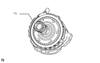
REMOVE UNDERDRIVE PLANETARY GEAR ASSEMBLY
-
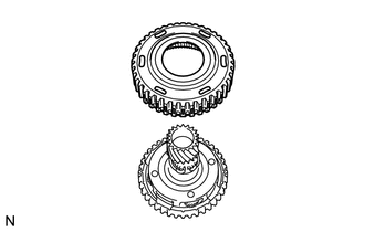
Remove the underdrive planetary gear assembly from the front oil pump assembly.
-
-
REMOVE NO. 3 BRAKE HUB
-
Remove the No. 3 brake hub from the underdrive planetary gear assembly.
-
*1 Thrust Needle Roller Race *2 Thrust Needle Roller Bearing Remove the thrust needle roller bearing and thrust needle roller race from the underdrive planetary gear assembly.
-
-
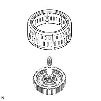
REMOVE PLANETARY SUN GEAR SUB-ASSEMBLY
-
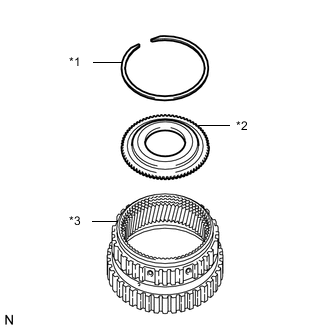
*1 Planetary Sun Gear Sub-assembly *2 Underdrive Planetary Gear Assembly *3 Snap Ring While expanding the snap ring with snap ring expander, remove the planetary sun gear sub-assembly from the underdrive planetary gear assembly.
-
Remove the snap ring from the underdrive planetary gear assembly.
-
-
INSPECT UNDERDRIVE PLANETARY GEAR ASSEMBLY
-
INSPECT PLANETARY SUN GEAR SUB-ASSEMBLY
-
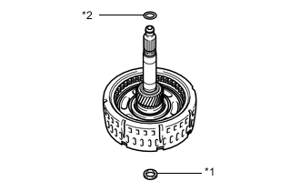
REMOVE INPUT SHAFT SUB-ASSEMBLY
-
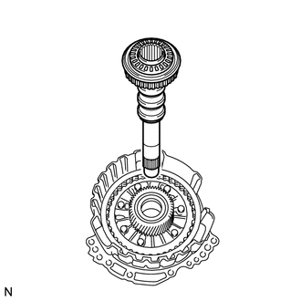
Remove the input shaft sub-assembly from the front oil pump assembly.
-
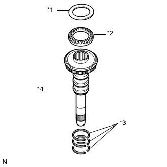
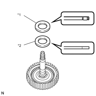
*1 Thrust Needle Roller Race *2 Thrust Needle Roller Bearing *3 Input Shaft Oil Seal Ring *4 Input Shaft Sub-assembly Remove the thrust needle roller bearing and thrust needle roller race from the input shaft sub-assembly.
-
Using a screwdriver with its tip wrapped with protective tape, remove the 3 input shaft oil seal rings from the input shaft sub-assembly.
-
-
REMOVE UNDERDRIVE PLANETARY SUN GEAR
-
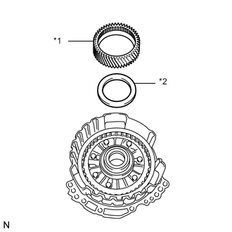
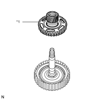
*1 Underdrive Planetary Sun Gear *2 Thrust Needle Roller Bearing Remove the underdrive planetary sun gear from the front oil pump assembly.
-
Remove the thrust needle roller bearing from the front oil pump assembly.
-
-
REMOVE NO. 1 BRAKE DISC
-
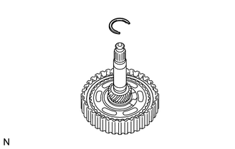
*1 Snap Ring *2 Brake Snap Ring Stopper Using a screwdriver with its tip wrapped with protective tape, remove the 2 snap rings and brake snap ring stopper from the front oil pump assembly.
-
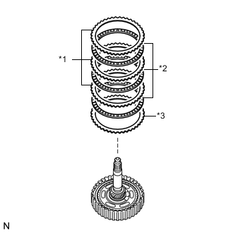
*1 No. 1 Brake Flange *2 No. 1 Brake Plate *3 No. 1 Brake Disc Remove the No. 1 brake flange, 4 No. 1 brake discs and 4 No. 1 brake plates from the front oil pump assembly.
-
-
INSPECT NO. 1 BRAKE DISC
-
REMOVE 2ND BRAKE PISTON RETURN SPRING SUB-ASSEMBLY
-
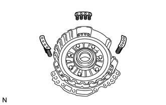
Remove the 3 2nd brake piston return spring sub-assemblies from the front oil pump assembly.
-
-
INSPECT 2ND BRAKE PISTON RETURN SPRING SUB-ASSEMBLY
-
REMOVE NO. 1 BRAKE PISTON
-
While holding the front oil pump assembly by hand, apply compressed air (392 kPa, 4.0 kgf/cm2, 57 psi) to the front oil pump assembly to remove the No. 1 brake piston.
-
*1 O-ring Using a screwdriver with its tip wrapped with protective tape, remove the 2 O-rings from the No. 1 brake piston.
-
-
REMOVE FRONT DIFFERENTIAL CASE
-
Remove the front differential case from the transaxle case sub-assembly.
-
-
REMOVE FRONT DIFFERENTIAL CASE FRONT TAPERED ROLLER BEARING (INNER RACE)
-
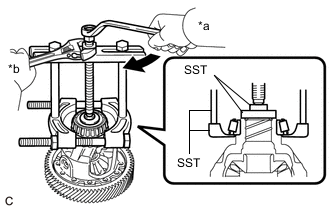
*a Turn *b Hold Using SST, remove the front differential case front tapered roller bearing (inner race) from the front differential case.
- SST
- 09950-00020
- 09950-00030
- 09950-40011 ( 09957-04010 )
- 09950-60010 ( 09951-00480 )
-
-
REMOVE FRONT DIFFERENTIAL CASE REAR TAPERED ROLLER BEARING (INNER RACE)
-
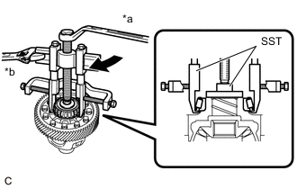
*a Turn *b Hold Using SST, remove the front differential case rear tapered roller bearing (inner race) from the front differential case.
- SST
- 09950-40011 ( 09951-04010, 09952-04010, 09953-04020, 09954-04010, 09955-04061, 09957-04010, 09958-04011 )
-
-
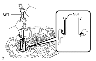
REMOVE COUNTER DRIVE GEAR NUT
-
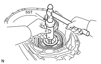
Using SST and a hammer, release the staked part of the front planetary gear assembly.
- SST
- 09930-00010
-
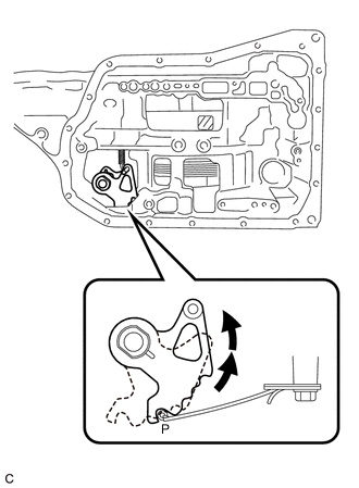
Turn the manual valve lever shaft sub-assembly 2 notches counterclockwise to set it to the P position as shown in the illustration.
-
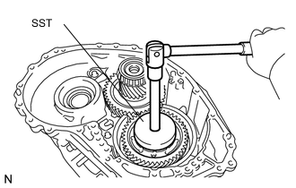
Using SST, remove the counter drive gear nut from the front planetary gear assembly.
- SST
- 09387-00130
-
-
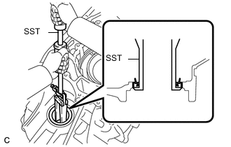
REMOVE COUNTER DRIVEN GEAR
-
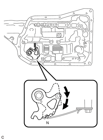
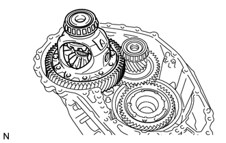
Turn the manual valve lever shaft sub-assembly 2 notches clockwise to set it to the N position as shown in the illustration.
-
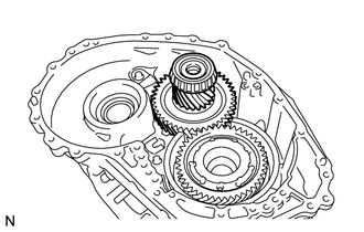
Remove the counter driven gear from the transaxle case sub-assembly.
-
-
REMOVE COUNTER DRIVEN GEAR FRONT TAPERED ROLLER BEARING (INNER RACE)
-
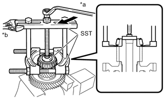
*a Turn *b Hold Using SST, remove the counter driven gear front tapered roller bearing (inner race) from the counter driven gear.
- SST
- 09950-00020
- 09950-00030
- 09950-60010 ( 09951-00400 )
-
-
REMOVE COUNTER DRIVEN GEAR REAR TAPERED ROLLER BEARING (INNER RACE)
-
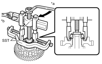
*a Turn *b Hold Using SST, remove the counter driven gear rear tapered roller bearing (inner race) from the counter driven gear.
- SST
- 09950-40011 ( 09951-04010, 09952-04010, 09953-04020, 09954-04010, 09955-04071, 09957-04010, 09958-04011 )
- 09950-60010 ( 09951-00320 )
-
-
REMOVE COUNTER DRIVEN GEAR REAR TAPERED ROLLER BEARING (OUTER RACE)
-
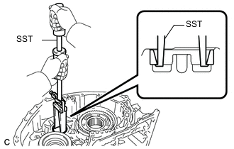
Using SST, remove the counter driven gear rear tapered roller bearing (outer race) from the transaxle case sub-assembly.
- SST
- 09308-00010
-
-
REMOVE PAWL SHAFT CLAMP
-
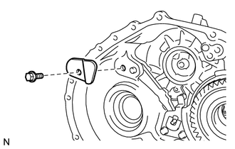
Remove the bolt and pawl shaft clamp from the transaxle case sub-assembly.
-
-
REMOVE PAWL STOPPER PLATE
-
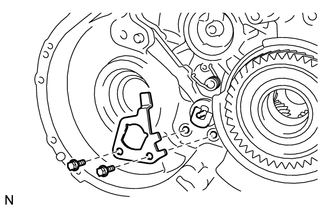
Remove the 2 bolts and pawl stopper plate from the transaxle case sub-assembly.
-
-
REMOVE PARKING LOCK SLEEVE
-
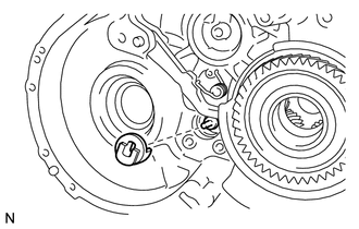
Remove the parking lock sleeve from the transaxle case sub-assembly.
-
-
REMOVE PARKING LOCK PAWL
-
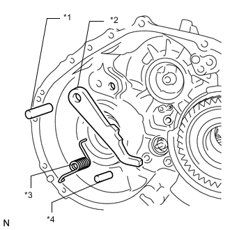
*1 Parking Lock Pawl Shaft *2 Parking Lock Pawl *3 Spring *4 Parking Lock Pawl Pin Remove the spring, parking lock pawl pin, parking lock pawl shaft and parking lock pawl from the transaxle case sub-assembly.
-
-
REMOVE FRONT DIFFERENTIAL CASE REAR TAPERED ROLLER BEARING (OUTER RACE)
-
Using SST, remove the front differential case rear tapered roller bearing (outer race) from the transaxle case sub-assembly.
- SST
- 09308-00010
-
-
REMOVE FRONT DRIVE SHAFT OIL SEAL LH
-
Using SST, remove the front drive shaft oil seal LH from the transaxle case sub-assembly.
- SST
- 09308-00010
-
-
REMOVE ONE-WAY CLUTCH ASSEMBLY
-
*a Protective Tape Using a screwdriver with its tip wrapped with protective tape, remove the snap ring from the transaxle case sub-assembly.
-
*1 One-way Clutch Assembly with Planetary Ring Gear *2 Thrust Needle Roller Bearing Remove the one-way clutch assembly with planetary ring gear from the transaxle case sub-assembly.
-
Remove the thrust needle roller bearing from the front planetary gear assembly.
-
-
INSPECT ONE-WAY CLUTCH ASSEMBLY
-
REMOVE PLANETARY RING GEAR
-
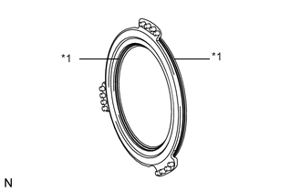
*1 One-way Clutch Assembly *2 Outer Race Retainer *3 Planetary Ring Gear Remove the planetary ring gear from the one-way clutch assembly.
-
Remove the outer race retainer from the one-way clutch assembly.
-
-
REMOVE PLANETARY RING GEAR FLANGE
-
*1 Snap Ring *2 Planetary Ring Gear Flange *3 Planetary Ring Gear Using a screwdriver with its tip wrapped with protective tape, remove the snap ring from the planetary ring gear.
-
Remove the planetary ring gear flange from the planetary ring gear.
-
-
REMOVE NO. 2 BRAKE DISC
-
*a Protective Tape Using a screwdriver with its tip wrapped with protective tape, remove the snap ring from the transaxle case sub-assembly.
-
*1 No. 2 Brake Flange *2 No. 2 Brake Plate *3 No. 2 Brake Disc Remove the No. 2 brake flange, 5 No. 2 brake discs and 5 No. 2 brake plates from the transaxle case sub-assembly.
-
-
INSPECT NO. 2 BRAKE DISC
-
REMOVE 1ST AND REVERSE BRAKE RETURN SPRING SUB-ASSEMBLY
-
*a Protective Tape Using a screwdriver with its tip wrapped with protective tape, remove the snap ring from the transaxle case sub-assembly.
-
Remove the 1st and reverse brake return spring sub-assembly from the transaxle case sub-assembly.
-
-
INSPECT 1ST AND REVERSE BRAKE RETURN SPRING SUB-ASSEMBLY
-
REMOVE NO. 2 BRAKE PISTON
-
Apply compressed air (392 kPa, 4.0 kgf/cm2, 57 psi) to the ATF hole to remove the No. 2 brake piston from the transaxle case sub-assembly.
-
*1 O-ring Using a screwdriver with its tip wrapped with protective tape, remove the 2 O-rings from the No. 2 brake piston.
-
-
REMOVE FRONT PLANETARY GEAR ASSEMBLY
-
Using SST and a press, remove the front planetary gear assembly from the transaxle case sub-assembly.
- SST
- 09950-60010 ( 09951-00580 )
- 09950-70010 ( 09951-07100 )
-
-
INSPECT FRONT PLANETARY GEAR ASSEMBLY
-
REMOVE COUNTER DRIVE GEAR
Note
Perform this procedure only when the counter drive gear bearing or transaxle case sub-assembly is replaced.
-
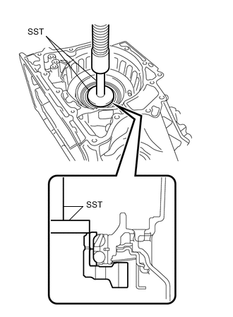
Using SST and a press, remove the counter drive gear and bearing inner race (rear side) from the transaxle case sub-assembly.
- SST
- 09950-60020 ( 09951-00710 )
- 09950-70010 ( 09951-07100 )
-
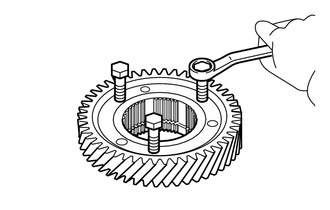
As shown in the illustration, tighten 3 service bolts evenly to make a clearance of approximately 20.0 mm (0.787 in.) between the counter drive gear and bearing inner race (front side).
-
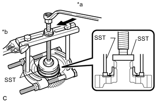
*a Turn *b Hold Using SST, remove the bearing inner race (front side) from the counter drive gear.
- SST
- 09950-00020
- 09950-00030
- 09950-60020 ( 09951-00710 )
-
-
REMOVE NO. 3 BRAKE PISTON
-
Using a screwdriver with its tip wrapped with protective tape, remove the snap ring from the transaxle case sub-assembly.
-
*1 Brake Piston Return Spring *2 No. 3 Brake Piston Remove the brake piston return spring from the transaxle case sub-assembly.
-
Remove the No. 3 brake piston from the transaxle case sub-assembly.
-
-
REMOVE MANUAL DETENT SPRING SUB-ASSEMBLY
-
Remove the bolt, cover and manual detent spring sub-assembly from the transaxle case sub-assembly.
-
-
REMOVE PARKING LOCK ROD SUB-ASSEMBLY
-
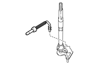
Remove the parking lock rod sub-assembly from the manual valve lever shaft sub-assembly.
Tech Tips
Align the protrusions with the notches on the manual valve lever shaft sub-assembly to remove the parking lock rod sub-assembly.
-
-
REMOVE MANUAL VALVE LEVER SHAFT SUB-ASSEMBLY
-
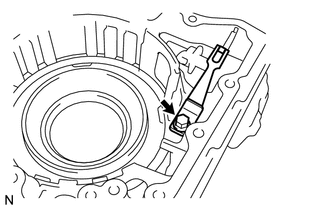
Using needle-nose pliers, remove the manual valve lever shaft retainer spring from the manual valve lever shaft sub-assembly.
-
Remove the manual valve lever shaft sub-assembly from the transaxle case sub-assembly.
-
-
REMOVE MANUAL VALVE LEVER SHAFT OIL SEAL
-
*a Protective Tape Using a screwdriver with its tip wrapped with protective tape, remove the manual valve lever shaft oil seal from the transaxle case sub-assembly.
-