AUTOMATIC TRANSAXLE ASSEMBLY INSTALLATION
CAUTION / NOTICE / HINT
CAUTION:
The engine assembly with automatic transaxle assembly is very heavy. Be sure to follow the procedure described in the repair manual, or the engine lifter may suddenly drop or the engine assembly with transaxle may fall off the engine lifter.
PROCEDURE
-
INSTALL TORQUE CONVERTER ASSEMBLY
-
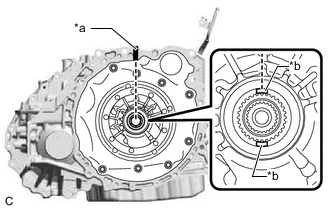
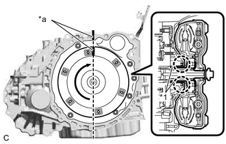
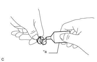
*a Matchmark *b Key Turn the front oil pump drive gear so that the key is at the top and place a matchmark on the transaxle housing to indicate the position of the key.
Note
To prevent damage to the stator shaft assembly when installing the torque converter assembly, make sure to place the matchmark on the correct location shown in the illustration.
-
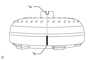
*a Groove *b Matchmark Place a matchmark on the torque converter assembly so that the position of its groove is clearly indicated.
-
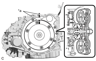
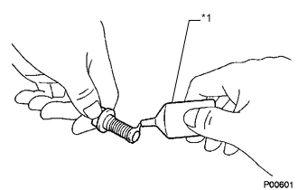
*1 Front Oil Pump Oil Seal *a Matchmark Align the matchmark on the transaxle housing with the one on the torque converter assembly and engage the splines of the input shaft with the turbine runner splines.
Note
-
Install the torque converter assembly to the input shaft while keeping it horizontal.
-
Do not damage the front oil pump oil seal.
-
-
*1 Front Oil Pump Oil Seal *a Matchmark Rotate the torque converter assembly approximately 180° and engage the splines of the stator shaft with the stator assembly.
Note
-
Install the torque converter assembly to the input shaft while keeping it horizontal.
-
Do not damage the front oil pump oil seal.
-
-
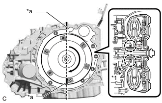
*1 Front Oil Pump Oil Seal *a Matchmark Rotate the torque converter assembly approximately 180° again, align the matchmark on the torque converter assembly with the one on the transaxle housing and insert the groove of the torque converter assembly into the key of the front oil pump drive gear.
Note
-
Do not push the torque converter assembly excessively when rotating it.
-
Install the torque converter assembly to the input shaft while keeping it horizontal.
-
Do not damage the front oil pump oil seal.
-
-
Clean the drive plate and torque converter assembly setting bolt holes.
-
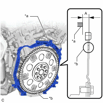
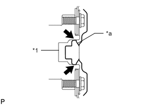
*a Engine Surface *b Drive Plate Surface Using a vernier caliper and straightedge, measure the dimension (A) between the automatic transaxle assembly contact surface of the engine assembly*a and the torque converter assembly contact surfaces of the drive plate*b.
-
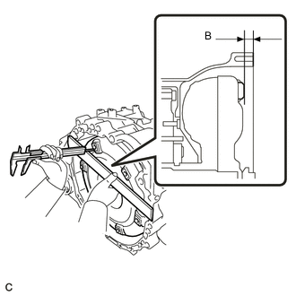
Using a vernier caliper and straightedge, measure the dimension (B) shown in the illustration and check that the dimension (B) is more than the dimension (A), which was measured in the previous step.
Standard A + 1 mm (0.0394 in.) or more Note
-
Make sure to deduct the thickness of the straightedge.
-
If the automatic transaxle assembly is installed to the engine assembly with the torque converter assembly not sufficiently inserted, the torque converter assembly may be damaged.
-
Do not include the thickness of the set block.
-
-
-
INSTALL SPEEDOMETER DRIVEN HOLE (ATM) COVER SUB-ASSEMBLY
-
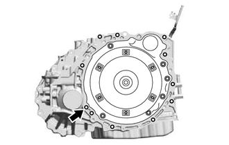
Apply ATF to a new O-ring and install it to the speedometer driven hole (ATM) cover sub-assembly.
-
Install the speedometer driven hole (ATM) cover sub-assembly to the transaxle case sub-assembly with the bolt.
- Torque:
- 5.5 N*m { 56 kgf*cm, 49 in.*lbf }
-
-
INSTALL NO. 1 TRANSMISSION CONTROL CABLE BRACKET
-
Install the No. 1 transmission control cable bracket to the transaxle case sub-assembly with the 2 bolts.
- Torque:
- 12 N*m { 122 kgf*cm, 9 ft.*lbf }
-
-
INSTALL ENGINE MOUNTING BRACKET LH
-
Clean the bolts and the installation holes in the engine mounting bracket LH.
-
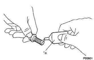
*a Adhesive Apply adhesive to 2 or 3 threads on the ends of the 4 bolts.
Adhesive Toyota Genuine Adhesive 1324, Three Bond 1324 or equivalent Note
In order to ensure proper installation of the 3 bolts, apply adhesive to the 3 bolts and install them within 10 minutes of adhesive application.
-
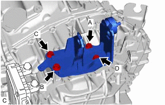
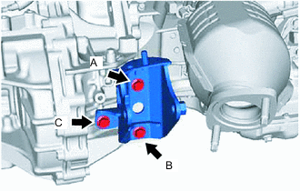
Install the engine mounting bracket LH to the transaxle case sub-assembly with the 4 bolts.
- Torque:
- 64 N*m { 653 kgf*cm, 47 ft.*lbf }
Note
Temporarily tighten the bolt (A), and then fully tighten the 4 bolts in the order of (B), (C), (D) and (A).
-
-
INSTALL WIRE HARNESS CLAMP BRACKET
-
Install the wire harness clamp bracket to the transaxle case sub-assembly with the bolt.
- Torque:
- 10 N*m { 102 kgf*cm, 7 ft.*lbf }
-
Install the wire harness clamp bracket to the engine mounting bracket LH with the bolt.
- Torque:
- for Flange Bolt
- 13 N*m { 133 kgf*cm, 10 ft.*lbf }
- for Bolt with Washer
- 8.0 N*m { 82 kgf*cm, 71 in.*lbf }
-
Install the 2 wire harness clamp brackets to the transaxle case sub-assembly with the 2 bolts.
- Torque:
- 10 N*m { 102 kgf*cm, 7 ft.*lbf }
-
-
INSTALL AUTOMATIC TRANSAXLE ASSEMBLY
CAUTION:
The automatic transaxle assembly is very heavy. Be sure to follow the procedure described in the repair manual, or the transmission jack may suddenly drop or a part may fall.
-
Using a transmission jack attachment, set the automatic transaxle assembly on a transmission jack.
Note
-
Secure the automatic transaxle assembly to the transmission jack using a suitable adapter, such as a rope or attachment.
-
To prevent the automatic transaxle oil pan sub-assembly from deforming, do not place any attachments under the automatic transaxle oil pan sub-assembly.
-
Hold the engine assembly with a suitable adapter, such as a rope, during the operation.
-
-
Clean and degrease the bolt and bolt hole in the transaxle housing.
-
*1 Crankshaft *a Torque Converter Assembly Centerpiece Apply clutch spline grease to the surface of the crankshaft that contacts the torque converter assembly centerpiece.
Clutch Spline Grease Toyota Genuine Clutch Spline Grease or equivalent Maximum Grease Amount Approximately 1 g (0.0353 oz.) -
Confirm that the 2 knock pins are installed to the engine assembly and are not damaged.
-
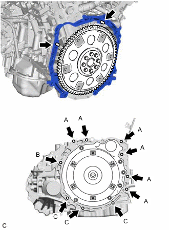
While keeping the engine assembly and automatic transaxle assembly horizontal, align the knock pins with the holes in the automatic transaxle assembly and temporarily install the 10 bolts shown in the illustration.
- Torque:
- Bolt (A)
- 64 N*m { 653 kgf*cm, 47 ft.*lbf }
- Bolt (B)
- 64 N*m { 653 kgf*cm, 47 ft.*lbf }
- Bolt (C)
- 43 N*m { 438 kgf*cm, 32 ft.*lbf }
Note
-
Make sure that the wire harness or other similar items are not pinched between the contact surfaces.
-
Do not forcibly pry on the automatic transaxle assembly.
-
Confirm that the 2 knock pins are installed to the automatic transaxle assembly contact surface of the engine cylinder block before installing the automatic transaxle assembly.
-
Check that the torque converter assembly rotates.
-
When tightening the bolts, make sure that the contact surfaces of the engine assembly and the automatic transmission assembly are in close contact with one another.
Tech Tips
Bolt length:
-
Bolt (A): 55 mm (2.17 in.)
-
Bolt (B): 50 mm (1.97 in.)
-
Bolt (C): 33 mm (1.30 in.)
-
*1 Adhesive 1324 Apply a few drops of adhesive to 2 or 3 threads at the tip of the bolt.
Adhesive Toyota Genuine Adhesive 1324, Three Bond 1324 or equivalent Note
In order to ensure proper sealing of the bolt, apply adhesive to the bolt and install them within 3 minutes of adhesive application.
-
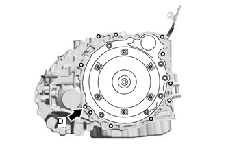
Install the bolt (D).
- Torque:
- 46 N*m { 469 kgf*cm, 34 ft.*lbf }
Tech Tips
Bolt length:
-
Bolt (D): 41 mm (1.61 in.)
-
-
INSTALL TRANSMISSION BREATHER SKIRT
-
Install the transmission breather skirt to the engine assembly with the 3 bolts.
- Torque:
- 7.5 N*m { 76 kgf*cm, 66 in.*lbf }
-
Connect the breather plug hose to the transmission breather skirt and slide the clip to secure it.
-
-
CONNECT WIRE HARNESS
-
Connect the wire harness to the transaxle case sub-assembly with the bolt.
- Torque:
- 12.5 N*m { 127 kgf*cm, 9 ft.*lbf }
-
Engage the clamp to connect the wire harness to the engine mounting bracket LH.
-
Engage the 2 clamps to connect the wire harness to the wire harness clamp bracket.
-
Connect the park/neutral position switch connector.
-
Engage the 2 clamps to connect the wire harness to the wire harness clamp bracket.
-
-
INSTALL TCM
-
INSTALL STARTER ASSEMBLY
-
INSTALL REAR ENGINE MOUNTING BRACKET
-
Install the rear engine mounting bracket to the transaxle case sub-assembly with the 3 bolts.
- Torque:
- 45 N*m { 459 kgf*cm, 33 ft.*lbf }
Note
Temporarily tighten the bolt (A), and then fully tighten the 3 bolts in the order of (B), (C) and (A).
-
-
INSTALL FRONT ENGINE MOUNTING BRACKET
-
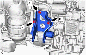
Install the front engine mounting bracket to the transaxle case sub-assembly with the 3 bolts.
- Torque:
- 45 N*m { 459 kgf*cm, 33 ft.*lbf }
Note
Temporarily tighten the bolt (A), and then fully tighten the 3 bolts in the order of (B), (C) and (A).
-
-
INSTALL MANIFOLD STAY
-
TEMPORARILY INSTALL REAR ENGINE MOUNTING INSULATOR
-
TEMPORARILY INSTALL FRONT ENGINE MOUNTING INSULATOR
-
INSTALL ENGINE ASSEMBLY WITH TRANSAXLE
-
INSTALL DRIVE PLATE AND TORQUE CONVERTER ASSEMBLY SETTING BOLT
-
Clean the threads of the 6 drive plate and torque converter assembly setting bolts.
-
*a Adhesive 1324 Apply a few drops of adhesive to 2 or 3 threads at the tip of the 6 drive plate and torque converter assembly setting bolts.
Adhesive Toyota Genuine Adhesive 1324, Three Bond 1324 or equivalent. Note
Install the torque converter assembly setting bolts within 3 minutes of applying adhesive.
-
Install the 6 drive plate and torque converter assembly setting bolts.
- Torque:
- 41 N*m { 418 kgf*cm, 30 ft.*lbf }
Tech Tips
Turn the crankshaft to gain access to the installation locations of each torque converter assembly setting bolt and install each bolt while holding the crankshaft pulley bolt with a wrench.
Note
First install the black colored drive plate and torque converter assembly setting bolt, and then the remaining 5 silver colored drive plate and torque converter assembly setting bolts.
-
-
INSTALL FLYWHEEL HOUSING UNDER COVER
-
CHECK AUTOMATIC TRANSAXLE SYSTEM
Note
If automatic transaxle assembly parts have been replaced, refer to Parts Replacement Compensation Table to determine if any additional operations are necessary.