AUTOMATIC TRANSAXLE ASSEMBLY REMOVAL
CAUTION / NOTICE / HINT
The necessary procedures (adjustment, calibration, initialization, or registration) that must be performed after parts are removed, installed, or replaced during the automatic transaxle assembly removal/installation are shown below.
| Replacement Part or Procedure | Necessary Procedures | Effects/Inoperative when not Performed | Link | |
|---|---|---|---|---|
| Battery terminal is disconnected/reconnected | Drive the vehicle until stop and start control is permitted (approximately 15 to 40 minutes) | Stop and start system | ||
| Memorize steering angle neutral point | Panoramic view monitor system | |||
| Initialize back door lock | Power door lock control system | |||
| Initialize servo motor | Air conditioning system | |||
| Reset slide door close position | Power slide door system | |||
| Reset back door close position | Power back door system | |||
| Replacement of ECM | Perform Vehicle Identification Number (VIN) or frame number registration |
|
||
| ECU Communication ID Registration (Immobiliser system) | Engine start function | See Service Bulletin for the registration method. | ||
| Perform code registration (Immobiliser system) |
|
See Service Bulletin for the registration method. | ||
|
Inspection After Repair |
|
||
| Replacement of automatic transaxle assembly | Perform the following procedures in the order shown:
|
|
Click here for Initialization Click here for Registration |
|
| Front wheel alignment adjustment |
|
|
||
| Work that changes the vehicle height such as replacement or removal/installation of the rear height control sensor sub-assembly LH or replacement of suspension components | Initialize headlight light control ECU sub-assembly LH | Headlight leveling function | ||
| Removal/installtaion of the radiator grille | Television camera view adjustment | Panoramic view monitor system | ||
| Replacement of TCM (If possible, read the transaxle compensation code from the previous TCM) |
Possible to read transaxle compensation code | Perform the following procedures in the order shown:
|
|
Click here for Initialization Click here for Registration |
| Impossible to read transaxle compensation code | Perform the following procedures in the order shown:
|
|||
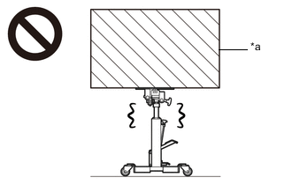
CAUTION:
-
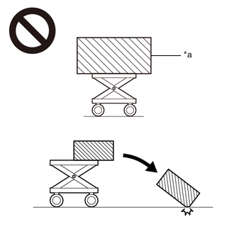
*a An Object Exceeding Weight Limit of Engine Lifter The engine assembly with automatic transaxle assembly is very heavy. Be sure to follow the procedure described in the repair manual, or the engine lifter may suddenly drop or the engine assembly with transaxle may fall off the engine lifter.
PROCEDURE
-
PRECAUTION
Note
If automatic transaxle assembly parts are replaced, refer to Parts Replacement Compensation Table to determine if any additional operations are necessary.
-
REMOVE FLYWHEEL HOUSING UNDER COVER
-
REMOVE DRIVE PLATE AND TORQUE CONVERTER ASSEMBLY SETTING BOLT
-
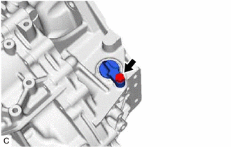
Remove the 6 drive plate and torque converter assembly setting bolts.
Tech Tips
-
Turn the crankshaft to gain access to the removable locations of the 6 drive plate and torque converter assembly setting bolts and remove each drive plate and torque converter assembly setting bolt while holding the crankshaft pulley bolt with a wrench.
-
There will be one black colored bolt.
-
-
-
REMOVE ENGINE ASSEMBLY WITH TRANSAXLE
-
INSTALL ENGINE HANGERS
-
REMOVE FRONT ENGINE MOUNTING INSULATOR
-
REMOVE REAR ENGINE MOUNTING INSULATOR
-
REMOVE MANIFOLD STAY
-
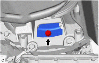
REMOVE FRONT ENGINE MOUNTING BRACKET
-
Remove the 3 bolts and front engine mounting bracket from the transaxle case sub-assembly.
-
-
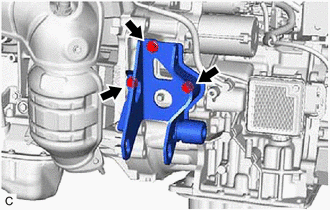
REMOVE REAR ENGINE MOUNTING BRACKET
-
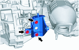
Remove the 3 bolts and rear engine mounting bracket from the transaxle case sub-assembly.
-
-
REMOVE STARTER ASSEMBLY
-
REMOVE TCM
-
DISCONNECT WIRE HARNESS
-
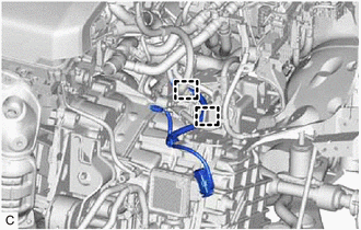
Disengage the 2 clamps to disconnect the wire harness from the wire harness clamp bracket.
-
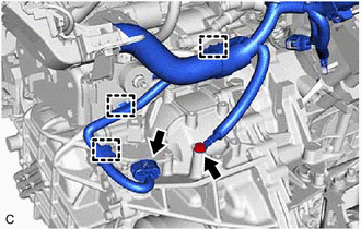
Disconnect the park/neutral position switch connector.
-
Disengage the 2 clamps to disconnect the wire harness from the wire harness clamp bracket.
-
Disengage the clamp to disconnect the wire harness from the engine mounting bracket LH.
-
Remove the bolt and disconnect the wire harness from the transaxle case sub-assembly.
-
-
REMOVE TRANSMISSION BREATHER SKIRT
-
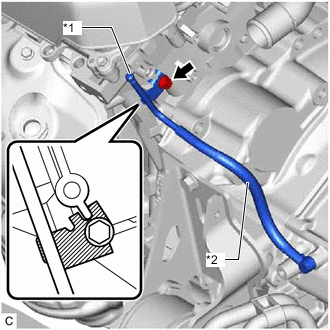
*1 Transmission Breather Skirt *2 Breather Hose Plug Slide the clip and disconnect the breather plug hose from the transmission breather skirt.
-
Remove the bolt and transmission breather skirt from the engine assembly.
-
-
REMOVE AUTOMATIC TRANSAXLE ASSEMBLY
CAUTION:
The automatic transaxle assembly is very heavy. Be sure to follow the procedure described in the repair manual, or the transmission jack may suddenly drop or a part may fall.
*a Object Exceeding Weight Limit of Transmission Jack
-
Using a transmission jack attachment, set the automatic transaxle assembly on a transmission jack.
Note
-
Secure the automatic transaxle assembly to the transmission jack using a suitable adapter, such as a rope or attachment.
-
To prevent the automatic transaxle oil pan sub-assembly from deforming, do not place any attachments under the automatic transaxle oil pan sub-assembly.
-
Hold the engine assembly with a suitable adapter, such as a rope, during the operation.
-
-
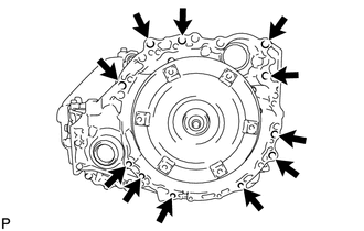
Remove the 11 bolts and automatic transaxle assembly.
Note
To prevent damage to the knock pins, do not pry between the automatic transaxle assembly and engine assembly.
-
-
REMOVE WIRE HARNESS CLAMP BRACKET
-
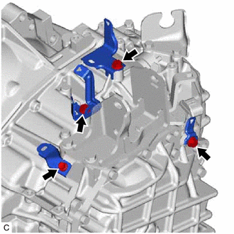
Remove the 2 bolts and 2 wire harness clamps brackets from the transaxle case sub-assembly.
-
Remove the bolt and wire harness clamp brackets from the engine mounting bracket LH.
-
Remove the bolt and wire harness clamp bracket from the rear transaxle cover sub-assembly.
-
-
REMOVE ENGINE MOUNTING BRACKET LH
-
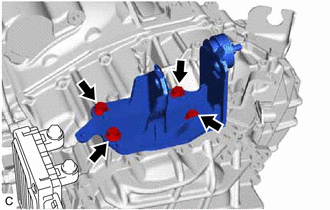
Remove the 4 bolts and engine mounting bracket LH from the transaxle case sub-assembly.
-
-
REMOVE NO. 1 TRANSMISSION CONTROL CABLE BRACKET
-
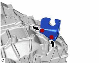
Remove the 2 bolts and No. 1 transmission control cable bracket from the transaxle case sub-assembly.
-
-
REMOVE SPEEDOMETER DRIVEN HOLE (ATM) COVER SUB-ASSEMBLY
-
Remove the bolt and speedometer driven hole (ATM) cover sub-assembly from the transaxle case sub-assembly.
-
Remove the O-ring from the speedometer driven hole (ATM) cover sub-assembly.
-
-
REMOVE TORQUE CONVERTER ASSEMBLY
-
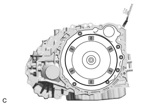
Remove the torque converter assembly from the automatic transaxle assembly.
Note
Remove the torque converter assembly from the input shaft horizontally.
-
-
INSPECT TORQUE CONVERTER ASSEMBLY
-
INSPECT DRIVE PLATE AND RING GEAR SUB-ASSEMBLY