DIFFERENTIAL OIL SEAL REPLACEMENT

CAUTION / NOTICE / HINT
The necessary procedures (adjustment, calibration, initialization, or registration) that must be performed after parts are removed, installed, or replaced during the front drive shaft oil seal removal/installation are shown below.
| Replacement Part or Procedure | Necessary Procedures | Effects/Inoperative when not Performed | Link |
|---|---|---|---|
| Gas leak from exhaust system is repaired | Inspection After Repair |
|
|
| Front wheel alignment adjustment |
|
|
PROCEDURE
-
REMOVE CONSOLE BOX ASSEMBLY (for Integrated Type)
-
REMOVE CENTER NO. 1 INSTRUMENT CLUSTER FINISH PANEL (for Separate Console Box Type)
-
REMOVE CENTER NO. 2 INSTRUMENT CLUSTER FINISH PANEL (for Separate Console Box Type)
-
REMOVE INSTRUMENT PANEL BOX ASSEMBLY (for Separate Console Box Type)
-
REMOVE INSTRUMENT CLUSTER FINISH PANEL ASSEMBLY (for Separate Console Box Type)
-
DISCONNECT HEATED OXYGEN SENSOR CONNECTOR (for Bank 1)
-
REMOVE REAR ENGINE UNDER COVER LH
-
DRAIN AUTOMATIC TRANSAXLE FLUID
-
Lift the vehicle.
Note
Set the vehicle on a lift so that the vehicle is kept level when it is lifted up (make sure that the tilt angle from the front to rear of the vehicle is within +/- 1°).
-
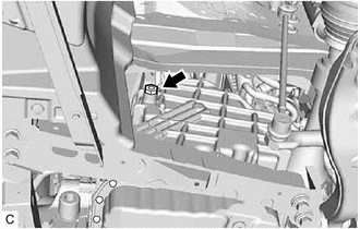
Remove the refill plug and gasket from the rear transaxle cover sub-assembly.
-
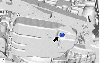
Using a 6 mm hexagon socket wrench, remove the overflow plug and gasket from the automatic transaxle oil pan sub-assembly.
-
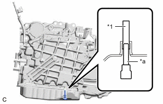
*1 No. 1 Transmission Oil Filler Tube *a 6 mm Hexagon Socket Wrench Using a 6 mm hexagon socket wrench, remove the No. 1 transmission oil filler tube from the automatic transaxle oil pan sub-assembly and drain the automatic transaxle fluid.
-
Using a 6 mm hexagon socket wrench, install the No. 1 transmission oil filler tube to the automatic transaxle oil pan sub-assembly.
- Torque:
- 1.7 N*m { 17 kgf*cm, 15 in.*lbf }
-
Using a 6 mm hexagon socket wrench, temporarily install the gasket and overflow plug to the automatic transaxle oil pan sub-assembly.
Tech Tips
Reuse the old gasket as the overflow plug will be removed again to adjust the fluid level.
-
Temporarily install the gasket and refill plug to the rear transaxle cover sub-assembly.
Tech Tips
Reuse the old gasket as the refill plug will be removed again to adjust the fluid level.
-
-
REMOVE FRONT NO. 3 EXHAUST PIPE SUB-ASSEMBLY
-
REMOVE FRONT EXHAUST PIPE ASSEMBLY
-
REMOVE FRONT DRIVE SHAFT ASSEMBLY
-
REMOVE DRIVE SHAFT BEARING BRACKET
-
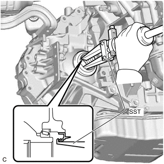
REMOVE FRONT DRIVE SHAFT OIL SEAL LH
-
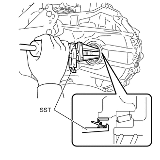
Using SST, remove the front drive shaft oil seal LH from the transaxle case sub-assembly.
- SST
- 09308-00010
Note
Be careful not to damage the transaxle case sub-assembly.
-
-
REMOVE FRONT DRIVE SHAFT OIL SEAL RH
-
Using SST, remove the front drive shaft oil seal RH from the transaxle case sub-assembly.
- SST
- 09308-00010
Note
Be careful not to damage the transaxle case sub-assembly.
-
-
INSTALL FRONT DRIVE SHAFT OIL SEAL LH
-
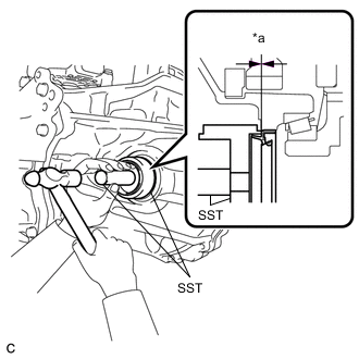
*a Depth Using SST and a hammer, install a new front drive shaft oil seal LH to the transaxle case sub-assembly.
- SST
- 09316-10010
- 09950-70010 ( 09951-07100 )
Standard Depth -0.5 to 0.5 mm (-0.0197 to 0.0197 in.) Note
-
Make sure that the front drive shaft oil seal LH is installed in the correct direction.
-
Make sure to install the front drive shaft oil seal LH as specified, otherwise malfunctions such as an automatic transaxle fluid leak will occur.
-
Coat the lip of the front drive shaft oil seal LH with MP grease.
-
-
INSTALL FRONT DRIVE SHAFT OIL SEAL RH
-
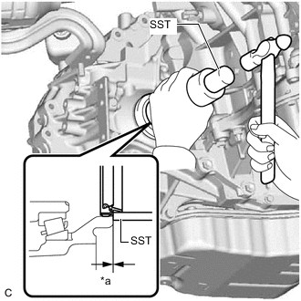
*a Depth Using SST and a hammer, install a new front drive shaft oil seal RH to the transaxle case sub-assembly.
- SST
- 09316-60011 ( 09316-00011 )
Standard Depth -0.5 to 0.5 mm (-0.0197 to 0.0197 in.) Note
-
Make sure that the front drive shaft oil seal RH is installed in the correct direction.
-
Make sure to install the front drive shaft oil seal LH as specified, otherwise malfunctions such as an automatic transaxle fluid leak will occur.
-
Coat the lip of the front drive shaft oil seal RH with MP grease.
-
-
INSTALL DRIVE SHAFT BEARING BRACKET
-
INSTALL FRONT DRIVE SHAFT ASSEMBLY
-
INSTALL FRONT EXHAUST PIPE ASSEMBLY
-
INSTALL FRONT NO. 3 EXHAUST PIPE SUB-ASSEMBLY
-
ADD AUTOMATIC TRANSAXLE FLUID
-
INSPECT AUTOMATIC TRANSAXLE FLUID LEAK
-
INSTALL REAR ENGINE UNDER COVER LH
-
CONNECT HEATED OXYGEN SENSOR CONNECTOR (for Bank 1)
-
INSTALL CONSOLE BOX ASSEMBLY (for Integrated Type)
-
INSTALL INSTRUMENT CLUSTER FINISH PANEL ASSEMBLY (for Separate Console Box Type)
-
INSTALL INSTRUMENT PANEL BOX ASSEMBLY (for Separate Console Box Type)
-
INSTALL CENTER NO. 2 INSTRUMENT CLUSTER FINISH PANEL (for Separate Console Box Type)
-
INSTALL CENTER NO. 1 INSTRUMENT CLUSTER FINISH PANEL (for Separate Console Box Type)