SHIFT LEVER INSTALLATION
PROCEDURE
-
INSTALL SHIFT LEVER ASSEMBLY
Note
Check that the park/neutral position switch assembly and the shift lever are in N.
-
Install the shift lever assembly to the No. 1 instrument panel brace sub-assembly with the 4 bolts.
- Torque:
- 12 N*m { 122 kgf*cm, 9 ft.*lbf }
-
Install the 3 screws.
-
Connect the transmission control switch connector.
Note
Be sure to securely connect the transmission control switch connector.
-
Connect the shift lock control ECU connector.
Note
Be sure to securely connect the shift lock control ECU connector.
-
-
CONNECT TRANSMISSION CONTROL CABLE ASSEMBLY
-
Turn the nut approximately 180° counterclockwise. While holding the nut in place, push in the stopper until it clicks twice.
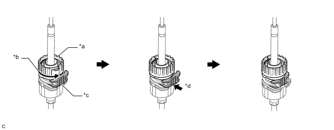
*a Nut *b Turn approximately 180° *c Stopper *d Push in Note
If the stopper cannot be pushed in, slightly turn the nut clockwise and then push in the stopper again.
-
Connect the transmission control cable assembly to the shift lever assembly. Check that the spring is positioned at (A) and push in the stopper.

*1 Shift Lever Assembly - - *a Spring *b Push in *c Stopper *d Nut Note
-
If the stopper cannot be pushed in, slightly turn the nut clockwise and then push in the stopper again.
-
Make sure that the transmission control cable assembly is securely locked.
-
-
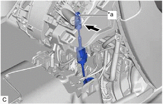
*a Pin Connect the transmission control cable assembly to the shift lever assembly.
Note
-
The shift lever should be in N.
-
Connect the transmission control cable assembly all the way to the base of the pin.
-
-
-
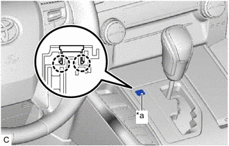
INSPECT SHIFT LEVER POSITION
-
ADJUST SHIFT LEVER POSITION
-
INSTALL INSTRUMENT CLUSTER FINISH PANEL ASSEMBLY (for Separate Console Box Type)
-
INSTALL INSTRUMENT PANEL BOX ASSEMBLY (for Separate Console Box Type)
-
INSTALL LOWER CENTER INSTRUMENT CLUSTER FINISH PANEL SUB-ASSEMBLY
-
INSTALL COMBINATION SWITCH ASSEMBLY
-
INSTALL AIR CONDITIONING CONTROL ASSEMBLY (for LHD)
-
INSTALL AIR CONDITIONING CONTROL ASSEMBLY (for RHD)
-
INSTALL CONSOLE BOX ASSEMBLY (for Integrated Type)
-
INSTALL SHIFT LEVER KNOB SUB-ASSEMBLY
-
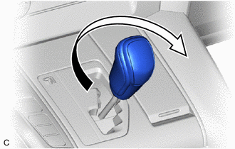
Turn the shift lever knob sub-assembly clockwise to install the shift lever knob sub-assembly.
-
-
INSTALL SHIFT LOCK RELEASE BUTTON COVER (for LHD)
-
*a Groove Engage the 2 claws to install the shift lock release button cover to the lower center instrument cluster finish panel sub-assembly.
Note
Install the shift lock release button cover with its groove facing the rear of the vehicle.
-
-
INSTALL SHIFT LOCK RELEASE BUTTON COVER (for RHD)
-
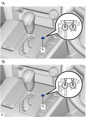
*A Type A *B Type B *a Groove Engage the 2 claws to install the shift lock release button cover to the lower center instrument cluster finish panel sub-assembly.
Note
Install the shift lock release button cover with its groove facing the rear of the vehicle.
-