STEERING ANGLE SENSOR INSTALLATION
CAUTION / NOTICE / HINT
Note
A lock pin is installed to a new steering sensor. Do not remove the lock pin before the steering sensor is installed to the spiral cable sub-assembly.
PROCEDURE
-
INSPECT SPIRAL CABLE SUB-ASSEMBLY
Note
If the steering sensor is installed to a misaligned spiral cable sub-assembly, DTCs for an abnormal steering sensor value such as DTC B1801, C1231 and DTC C1433 are stored and it is impossible to repair them. If this happens, replace the spiral cable with sensor sub-assembly with a new one.
-
Check if the spiral cable sub-assembly is centered.
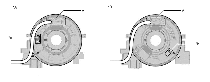
*A w/o Steering Heater *B w/ Steering Heater *a Colored Part (Yellow) *b Flat Cable Tech Tips
When the spiral cable sub-assembly is centered, the part indicated by (A) is positioned at the top and the colored part (yellow) or flat cable shown in the illustration can be seen.
-
If the spiral cable sub-assembly is not centered, center it.
-
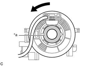
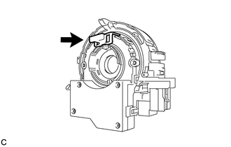
*a Interlock While pushing on the interlock shown in the illustration, rotate the spiral cable sub-assembly counterclockwise slowly by hand until it stops.
Note
-
When rotating the spiral cable sub-assembly, make sure to push on the interlock shown in the illustration to release the interlock mechanism.
-
Do not turn the spiral cable sub-assembly using the airbag wire harness.
-
If the spiral cable sub-assembly cannot be centered, it is possible that the spiral cable sub-assembly is broken. Replace the spiral cable sub-assembly or spiral cable with sensor sub-assembly with a new one.
-
-
While pushing on the interlock shown in the illustration, rotate the spiral cable sub-assembly clockwise approximately 2.5 times to the position where the alignment marks are aligned and the colored part (yellow) or flat cable shown in the illustration can be seen.
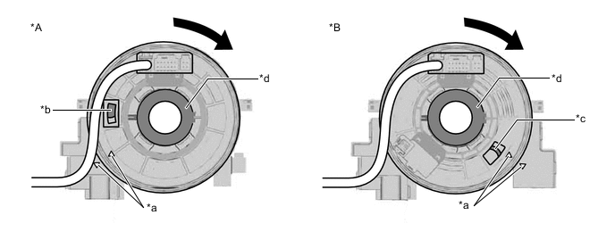
*A w/o Steering Heater *B w/ Steering Heater *a Alignment Mark *b Colored Part (Yellow) *c Flat Cable *d Interlock Tech Tips
The spiral cable sub-assembly can be rotated approximately 2.5 turns to both the left and right from the center.
-
-
-
INSTALL STEERING SENSOR
-
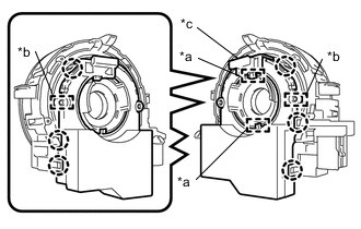
*a Guide *b Pin *c Lock Pin Align the 2 pins and 2 guides, and engage the 6 claws to install the steering sensor to the spiral cable sub-assembly.
Note
-
Do not remove the lock pin before the steering sensor is installed to the spiral cable sub-assembly.
-
Do not damage the pins of the spiral cable sub-assembly and guides of the steering sensor.
-
The spiral cable sub-assembly can be rotated up to 30° even when the interlock is engaged. Therefore, make sure that both guides are aligned properly when installing the steering sensor to the spiral cable sub-assembly.
-
-
Remove the lock pin from the steering sensor.
-
-
INSTALL SPIRAL CABLE WITH SENSOR SUB-ASSEMBLY