AUTOMATIC TRANSAXLE SYSTEM TERMINALS OF ECU

-
TCM

Tech Tips
The standard voltage between each pair of TCM terminals is shown in the table below.
The appropriate conditions for checking each pair of terminals are also indicated. The result of checks should be compared with the standard voltage for that pair of terminals shown in the "Specified Condition" column.
Use the illustration above as a reference for the TCM terminals.
Terminal No. (Symbol) Wiring Color Terminal Description Condition Specified Condition D39-1 (BATT) - D39-8 (E1) W - BR Battery (for measuring battery voltage and for TCM memory) Always 9 to 14 V D39-3 (SPD) - D39-8 (E1) G - BR Speed signal from combination meter Vehicle being driven Pulse generation D39-6 (CAN+) - D39-8 (E1) B - BR CAN communication line Engine switch on (IG) Pulse generation D39-7 (CAN-) - D39-8 (E1) W - BR CAN communication line Engine switch on (IG) Pulse generation D39-8 (E1) - Body ground BR - Body ground Ground Always Below 1 Ω D39-9 (E01) - Body ground W-B - Body ground Ground Always Below 1 Ω D39-10 (STA) - D39-8 (E1) Y - BR Starter signal Cranking (Shift lever in P or N, engine switch START) 11 to 14 V Engine switch on (IG) and shift lever not in P or N Below 2 V D39-11 (NSW) - D39-8 (E1) R - BR Park/neutral position switch signal Engine switch on (IG) and shift lever in P or N Below 2 V Engine switch on (IG) and shift lever not in P or N 11 to 14 V D39-12 (STP) - D39-8 (E1) GR - BR Stop light switch signal Brake pedal depressed 7.5 to 14 V Brake pedal released Below 1.5 V D39-13 (IGSW) - D39-8 (E1) B - BR IG signal Engine switch on (IG) 9 to 14 V D39-15 (R) - D39-8 (E1) P - BR R shift position switch signal Engine switch on (IG) and shift lever in R 11 to 14 V Engine switch on (IG) and shift lever not in R Below 1 V D39-16 (D) - D39-8 (E1) G - BR D shift position switch signal Engine switch on (IG) and shift lever in D or S 11 to 14 V Engine switch on (IG) and shift lever not in D and S Below 1 V D39-18 (+B) - D39-8 (E1) W - BR Power source of TCM Engine switch on (IG) 9 to 14 V -
ECM
Tech Tips
The standard voltage between each pair of ECM terminals is shown in the table below.
The appropriate conditions for checking each pair of terminals are also indicated. The result of checks should be compared with the standard voltage for that pair of terminals shown in the "Specified Condition" column.
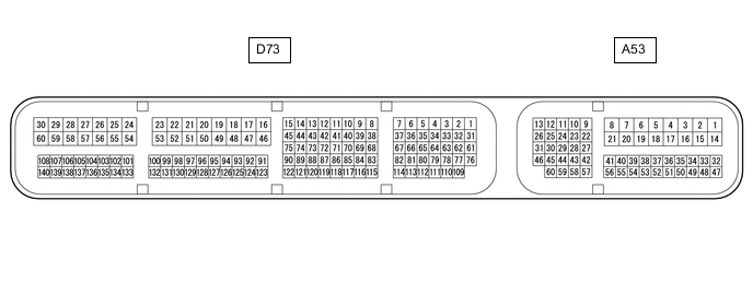
Use the illustration below as a reference for the ECM terminals.
Terminal No. (Symbol) Wiring Color Terminal Description Condition Specified Condition A53-37 (S) - D73-49 (E1) BR - BR S shift position switch signal Engine switch on (IG) and shift lever in S 11 to 14 V Engine switch on (IG) and shift lever not in S Below 1 V A53-34 (SFTU) - D73-49 (E1) P - BR Up shift switch signal Engine switch on (IG) and shift lever in S 11 to 14 V Engine switch on (IG) and shift lever held in "+" (Up shift) Below 1 V A53-50 (SFTD) - D73-49 (E1) GR - BR Down shift switch signal Engine switch on (IG) and shift lever in S 11 to 14 V Engine switch on (IG) and shift lever held in "-" (Down shift) Below 1 V