ENGINE STOP AND START ECU REMOVAL
CAUTION / NOTICE / HINT
The necessary procedures (adjustment, calibration, initialization, or registration) that must be performed after parts are removed, installed, or replaced during the engine stop and start ECU removal/installation are shown below.
| Replacement Part or Procedure | Necessary Procedures | Effects/Inoperative when not Performed | Link |
|---|---|---|---|
| Battery terminal is disconnected / reconnected | Drive the vehicle until stop and start control is permitted (approximately 5 to 60 minutes) | Stop and Start System (for 2AR-FE) | |
| Stop and Start System (for 2GR-FKS) | |||
| Memorize steering angle neutral point | Panoramic view monitor system | ||
| Initialize back door lock | Power door lock control system | ||
| Initialize servo motor | Air conditioning system | ||
| Reset slide door close position | Power slide door system | ||
| Reset back door close position | Power back door system | ||
| Replacement of engine stop and start ECU |
|
Stop and start system | Click here for 2AR-FE Click here for 2GR-FKS |
PROCEDURE
-
PRECAUTION
Note
After turning the engine switch off, waiting time may be required before disconnecting the cable from the negative (-) battery terminal. Therefore, make sure to read the disconnecting the cable from the negative (-) battery terminal notices before proceeding with work.
-
READ NUMBER OF STARTER OPERATIONS
-
for 2AR-FE
-
for 2GR-FKS
-
-
DISCONNECT CABLE FROM NEGATIVE BATTERY TERMINAL
Note
When disconnecting the cable, some systems need to be initialized after the cable is reconnected.
-
REMOVE NO. 2 INSTRUMENT PANEL UNDER COVER SUB-ASSEMBLY
-
for LHD:
-
for RHD:
-
-
REMOVE GLOVE COMPARTMENT DOOR ASSEMBLY
-
for LHD:
-
for RHD:
-
-
REMOVE ENGINE STOP AND START SOLENOID FILTER (for LHD)
-
REMOVE ENGINE STOP AND START ECU
-
for LHD:
-
Disconnect each connector.
-
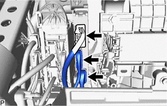
Disconnect the 3 engine stop and start ECU connectors.
-
Remove the bolt, nut and engine stop and start ECU.
-
-
for RHD:
-
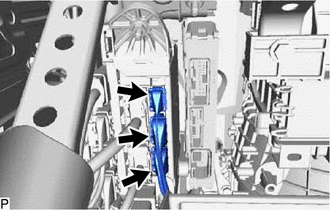
Disconnect the 3 engine stop and start ECU connectors.
-
Disconnect the 3 main body ECU (multiplex network body ECU) connectors.
-
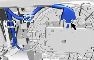
Disconnect the blower with fan motor sub-assembly connector and disengage the 2 clamps.
-
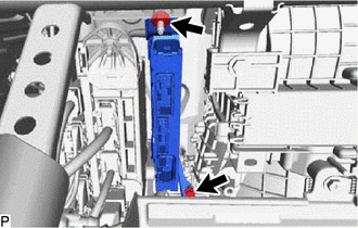
Remove the bolt, nut and engine stop and start ECU.
-
-