OIL PUMP REMOVAL

CAUTION / NOTICE / HINT
The necessary procedures (adjustment, calibration, initialization, or registration) that must be performed after parts are removed, installed, or replaced during the oil pump removal/installation are shown below.
| Replacement Part or Procedure | Necessary Procedures | Effects/Inoperative when not Performed | Link |
|---|---|---|---|
| Battery terminal is disconnected/reconnected | Memorize steering angle neutral point | Panoramic view monitor system | |
| Initialize back door lock | Power door lock control system | ||
| Initialize servo motor | Air conditioning system | ||
| Reset slide door close position | Power slide door system | ||
| Reset back door close position | Power back door system | ||
| Replacement of ECM | Perform Vehicle Identification Number (VIN) or frame number registration |
|
|
| ECU Communication ID Registration (Immobiliser system) | Engine start function | See Service Bulletin for the registration method. | |
| Perform code registration (Immobiliser system) |
|
See Service Bulletin for the registration method. | |
|
Inspection After Repair |
|
|
| Replacement of automatic transaxle assembly | Perform the following procedures in the order shown:
|
|
Click here for Initialization Click here for Registration |
| Front wheel alignment adjustment |
|
|
|
| Work that changes the vehicle height such as replacement or removal/installation of the rear height control sensor sub-assembly LH or replacement of suspension components | Initialize headlight light control ECU sub-assembly LH | Headlight leveling function | |
| Removal/installtaion of the radiator grille | Television camera view adjustment | Panoramic view monitor system |
PROCEDURE
-
REMOVE OIL PAN SUB-ASSEMBLY
-
REMOVE TIMING CHAIN COVER SUB-ASSEMBLY
-
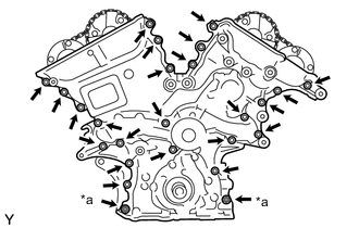
*a Nut Remove the 23 bolts and 2 nuts shown in the illustration.
-
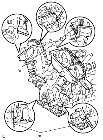
*a Protective Tape Remove the timing chain cover sub-assembly by prying between the timing chain cover sub-assembly and cylinder head sub-assembly or cylinder block sub-assembly with a screwdriver.
Note
Be careful not to damage the contact surfaces of the cylinder head sub-assembly, cylinder block sub-assembly and timing chain cover sub-assembly.
Tech Tips
Tape the screwdriver tip before use.
-
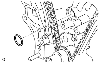
Remove the gasket.
-
-
REMOVE TIMING CHAIN CASE OIL SEAL
-
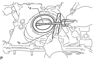
*a Protective Tape *b Wooden Block Using a screwdriver, pry out the timing chain case oil seal.
Tech Tips
Tape the screwdriver tip before use.
-