VEHICLE STABILITY CONTROL SYSTEM, Diagnostic DTC:C1476, C1477, C1479

| DTC Code | DTC Name |
|---|---|
| C1476 | Brake Booster Pressure Sensor Circuit Low |
| C1477 | Brake Booster Pressure Sensor Circuit High |
| C1479 | Abnormal Power Supply Voltage in Brake Booster Pressure Sensor |
DESCRIPTION
Brake booster pressure sensor (vacuum sensor) detects the pressure in the brake booster.
If a malfunction is detected in the brake booster pressure sensor (vacuum sensor), the fail-safe function prohibits ABS, brake assist, TRC and VSC, and turns the warning and slip indicator lights on.
Tech Tips
EBD control will continue to the extent that EBD control is possible even after ABS is prohibited.
| DTC No. | Detection Item | DTC Detection Condition | Trouble Area | Note |
|---|---|---|---|---|
| C1476 | Brake Booster Pressure Sensor Circuit Low | The brake booster pressure sensor input voltage is less than 0.7 V for 1.2 seconds or more. |
|
for 2AR-FE |
| C1477 | Brake Booster Pressure Sensor Circuit High | The brake booster pressure sensor input voltage is more than 4.2 V for 1.2 seconds or more. |
|
for 2AR-FE |
| C1479 | Abnormal Power Supply Voltage in Brake Booster Pressure Sensor | The brake booster pressure sensor power supply voltage is more than 5.2 V or less than 4.8 V for 1.2 seconds or more. |
|
for 2AR-FE |
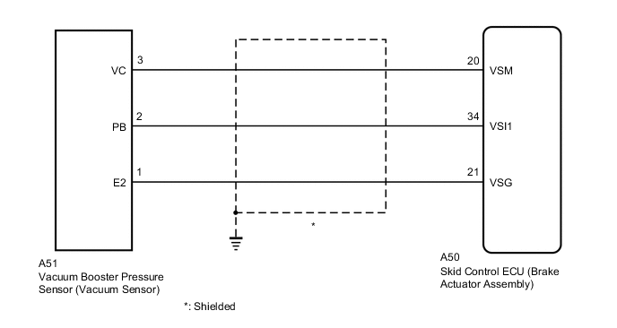
WIRING DIAGRAM
CAUTION / NOTICE / HINT
Note
When replacing the skid control ECU (brake actuator assembly), perform zero point calibration and store system information.
PROCEDURE
-
CHECK HARNESS AND CONNECTOR (BRAKE ACTUATOR ASSEMBLY - VACUUM BOOSTER PRESSURE SENSOR (VACUUM SENSOR))
-
Make sure that there is no looseness at the locking part and the connecting part of the connectors.
-
Disconnect the A50 skid control ECU (brake actuator assembly) connector.
-
Disconnect the A51 vacuum booster pressure sensor (vacuum sensor) connector.
-
Measure the resistance according to the value(s) in the table below.
Standard Resistance Tester Connection Condition Specified Condition A50-20 (VSM) - A51-3 (VC) Always Below 1 Ω A50-20 (VSM) or A51-3 (VC) - Body ground Always 10 kΩ or higher A50-34 (VSI1) - A51-2 (PB) Always Below 1 Ω A50-34 (VSI1) or A51-2 (PB) - Body ground Always 10 kΩ or higher A50-21 (VSG) - A51-1 (E2) Always Below 1 Ω A50-21 (VSG) or A51-1 (E2) - Body ground Always 10 kΩ or higher Result Proceed to OK NG
NG 
REPAIR OR REPLACE HARNESS OR CONNECTOR
OK 
-
-
INSPECT BRAKE ACTUATOR ASSEMBLY (SENSOR POWER SUPPLY OUTPUT)
-
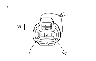
*a Front view of wire harness connector
(to Vacuum Booster Pressure Sensor (Vacuum Sensor))
Reconnect the A50 skid control ECU (brake actuator assembly) connector.
-
Measure the voltage according to the value(s) in the table below.
Standard Voltage Tester Connection Condition Specified Condition A51-3 (VC) - A51-1 (E2) Engine switch on (IG) 4.75 to 5.25 V Result Proceed to OK NG
OK
REPLACE VACUUM BOOSTER PRESSURE SENSOR (VACUUM SENSOR) Click here
NG
REPLACE BRAKE ACTUATOR ASSEMBLY Click here
-