FRONT SPEED SENSOR REMOVAL
CAUTION / NOTICE / HINT
The necessary procedures (adjustment, calibration, initialization, or registration) that must be performed after parts are removed, installed, or replaced during the front speed sensor removal/installation are shown below.
| Replacement Part or Procedure | Necessary Procedures | Effects/Inoperative when not Performed | Link |
|---|---|---|---|
| Disconnect cable from negative battery terminal | Drive the vehicle until stop and start control is permitted (approximately 15 to 40 minutes) | Stop and start system | |
| Memorize steering angle neutral point | Panoramic view monitor system | ||
| Initialize back door lock | Power door lock control system | ||
| Initialize servo motor | Air Conditioning System | ||
| Reset slide door close position | Power slide door system | ||
| Reset back door close position | Power back door system |
CAUTION / NOTICE / HINT
Tech Tips
-
Use the same procedure for the RH side and LH side.
-
The following procedure is for the LH side.
-
The front speed sensor rotor is a component of the front axle hub sub-assembly. If the front speed sensor rotor is malfunctioning, replace the front axle hub sub-assembly.
PROCEDURE
-
PRECAUTION
Note
After turning the engine switch off, waiting time may be required before disconnecting the cable from the negative (-) battery terminal. Therefore, make sure to read the disconnecting the cable from the negative (-) battery terminal notices before proceeding with work.
-
DISCONNECT CABLE FROM NEGATIVE BATTERY TERMINAL
Note
When disconnecting the cable, some systems need to be initialized after the cable is reconnected.
-
REMOVE FRONT WHEEL
-
SEPARATE FRONT FENDER SPLASH SHIELD SUB-ASSEMBLY
-
Remove the screw and separate the front fender splash shield sub-assembly.
-
-
REMOVE FRONT SPEED SENSOR
-
Turn back the front fender splash shield sub-assembly.
-
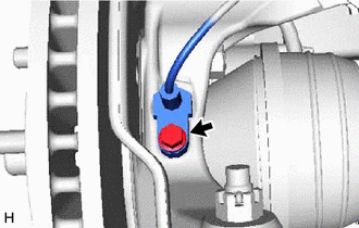
Disconnect the connector.
-
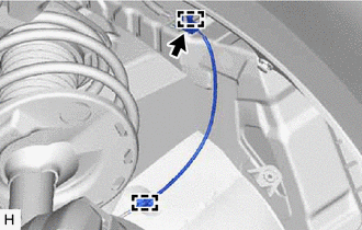
Disengage the 2 clamps from the vehicle body.
-
Disengage the clamp from the vehicle body.
-
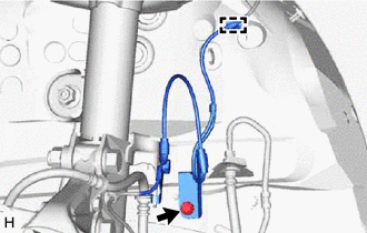
Remove the bolt and separate the front speed sensor clamp.
-
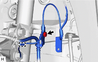
Remove the bolt and separate the front flexible hose and front speed sensor clamp from the front shock absorber assembly.
-
Disengage the clamp from the front shock absorber assembly.
-
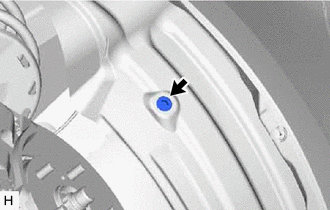
Remove the bolt and front speed sensor from the steering knuckle.
Note
-
Prevent foreign matter from attaching to the front speed sensor tip.
-
Clean the front speed sensor installation hole and the contact surfaces every time the front speed sensor is removed.
-
-