BRAKE ACTUATOR REMOVAL
CAUTION / NOTICE / HINT
The necessary procedures (adjustment, calibration, initialization, or registration) that must be performed after parts are removed, installed, or replaced during the brake actuator assembly removal/installation are shown below.
| Replacement Part or Procedure | Necessary Procedures | Effects/Inoperative when not Performed | Link |
|---|---|---|---|
| Replacement of brake actuator assembly | Perform yaw rate and acceleration sensor zero point calibration and store system information. |
|
|
| Disconnect cable from negative battery terminal | Drive the vehicle until stop and start control is permitted (approximately 15 to 40 minutes) | Stop and start system | |
| Memorize steering angle neutral point | Panoramic view monitor system | ||
| Initialize back door lock | Power door lock control system | ||
| Initialize servo motor | Air Conditioning System | ||
| Reset slide door close position | Power slide door system | ||
| Reset back door close position | Power back door system |
PROCEDURE
-
PRECAUTION
Note
After turning the engine switch off, waiting time may be required before disconnecting the cable from the negative (-) battery terminal. Therefore, make sure to read the disconnecting the cable from the negative (-) battery terminal notices before proceeding with work.
-
DISCONNECT CABLE FROM NEGATIVE BATTERY TERMINAL
Note
When disconnecting the cable, some systems need to be initialized after the cable is reconnected.
-
REMOVE WINDSHIELD WIPER MOTOR AND LINK ASSEMBLY
for LHD: Click here
for RHD: Click here
-
SEPARATE BRAKE MASTER CYLINDER RESERVOIR ASSEMBLY
for LHD: Click here
for RHD: Click here
-
REMOVE NO. 1 HEATER AIR DUCT SPLASH SHIELD SEAL
for LHD: Click here
for RHD: Click here
-
REMOVE NO. 2 HEATER AIR DUCT SPLASH SHIELD SEAL
for LHD: Click here
for RHD: Click here
-
REMOVE OUTER COWL TOP PANEL SUB-ASSEMBLY
for LHD: Click here
for RHD: Click here
-
REMOVE BATTERY
for 2AR-FE: Click here
for 2GR-FE: Click here
-
REMOVE AIR CLEANER CAP SUB-ASSEMBLY (for 2AR-FE)
-
REMOVE AIR CLEANER CASE SUB-ASSEMBLY (for 2AR-FE)
-
REMOVE V-BANK COVER SUB-ASSEMBLY (for 2GR-FE)
-
REMOVE AIR CLEANER CAP WITH AIR CLEANER HOSE (for 2GR-FE)
-
REMOVE AIR CLEANER CASE SUB-ASSEMBLY (for 2GR-FE)
-
DRAIN BRAKE FLUID
Note
If brake fluid leaks onto any painted surface, immediately wash it off.
-
REMOVE BRAKE ACTUATOR WITH BRACKET
-
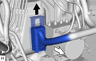

Release the lock lever 
Disconnect the connector Release the lock lever and disconnect the connector from the brake actuator assembly.
Note
Be careful not to allow any brake fluid to enter the connector.
-
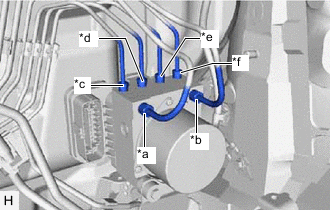
*a for LHD: From 1st Chamber of Brake Master Cylinder Sub-assembly
for RHD: From 2nd Chamber of Brake Master Cylinder Sub-assembly
*b for LHD: From 2nd Chamber of Brake Master Cylinder Sub-assembly
for RHD: From 1st Chamber of Brake Master Cylinder Sub-assembly
*c To Front Wheel Cylinder Assembly LH *d To Rear Wheel Cylinder Assembly RH *e To Rear Wheel Cylinder Assembly LH *f To Front Wheel Cylinder Assembly RH Use tags or make a memo to identify the places to reconnect the brake lines.
-
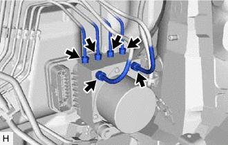
Using a union nut wrench, disconnect the 6 brake lines from the brake actuator assembly.
-

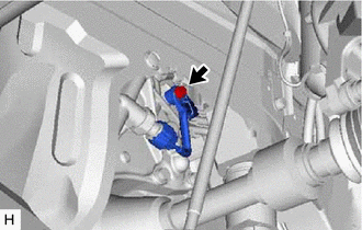
Disengage the clamp from the brake actuator bracket assembly.
-
for 2AR-FE:
-
Remove the bolt to separate the engine wire.
Tech Tips
It is not necessary to remove the connector or clamp from the engine wire.
-
-
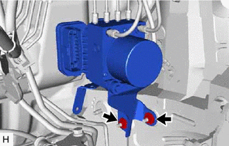
Remove the 2 nuts and brake actuator with bracket from the vehicle body.
Note
-
Do not damage the brake lines.
-
Do not hold the brake actuator assembly by the connector.
Tech Tips
-
Remove the brake actuator with bracket while avoiding the brake lines.
-
for 2AR-FE:
Hold the engine wire separated in step (b) to insert the tool from the bottom of the vehicle.
-
-
-
REMOVE BRAKE ACTUATOR ASSEMBLY
-
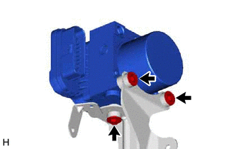
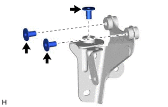
Remove the 3 bolts and brake actuator assembly from the brake actuator bracket assembly.
-
-
REMOVE BRAKE ACTUATOR BOLT CUSHION
-
Remove the 3 brake actuator case collars from the brake actuator bolt cushions.
-
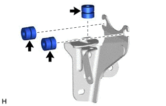
Remove the 3 brake actuator bolt cushions from the brake actuator bracket assembly.
-