EMISSION CONTROL SYSTEM ON-VEHICLE INSPECTION
CAUTION / NOTICE / HINT
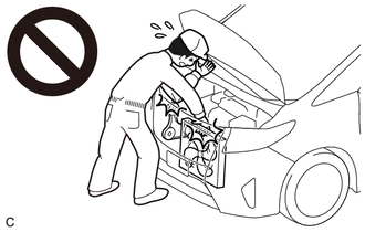
CAUTION:
To prevent injury due to contact with an operating V-ribbed belt or cooling fan, keep your hands and clothing away from the V-ribbed belt and cooling fans when working in the engine compartment with the engine running or the engine switch on (IG).
PROCEDURE
-
INSPECT FUEL CUT OPERATION
CAUTION:
To prevent injury due to contact with an operating V-ribbed belt or cooling fan, keep your hands and clothing away from the V-ribbed belt and cooling fans when working in the engine compartment with the engine running or the engine switch on (IG).
-
Increase the engine speed to approximately 3000 rpm.
-
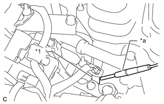
*1 Fuel Injector Assembly *a Sound Scope Use a sound scope to check for fuel injector assembly operating sounds.
-
When the accelerator pedal is fully released, check that fuel injector assembly operating sounds stop momentarily and then resume.
Standard Item Specified Condition Fuel cut-off engine speed 2500 rpm or higher Fuel injection restart engine speed 1400 rpm If the result is not as specified, check the fuel injector assemblies, wire harness and ECM.
-
-
VISUALLY CHECK HOSES, CONNECTIONS AND GASKETS
-
Visually check that the hoses, connections and gaskets have no cracks, leaks or damage.
Note
-
Detachment or other problems with the engine oil level dipstick, oil filler cap sub-assembly, ventilation hose or other components may cause the engine to run improperly.
-
Air suction caused by disconnections, looseness or cracks in any part of the air induction system between the throttle body with motor assembly and cylinder head sub-assembly will cause engine failure or engine malfunctions.
If any defects are found, replace parts as necessary.
-
-
-
INSPECT EVAPORATIVE EMISSION CONTROL SYSTEM
CAUTION:
To prevent injury due to contact with an operating V-ribbed belt or cooling fan, keep your hands and clothing away from the V-ribbed belt and cooling fans when working in the engine compartment with the engine running or the engine switch on (IG).
-
Connect the GTS to the DLC3.
-
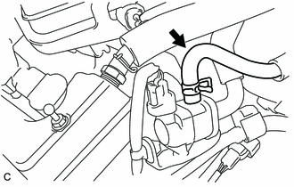
Slide the clip and disconnect the No. 2 fuel vapor feed hose from the purge valve (purge VSV).
-
Start the engine.
-
Turn the GTS on.
-
Enter the following menus: Powertrain / Engine / Active Test / Activate the VSV for Evap Control.
Powertrain > Engine > Active TestTester Display Activate the VSV for Evap Control -
Check that vacuum occurs at the purge valve (purge VSV) port.
-
If vacuum does not occur, check the following items.
-
Purge valve (purge VSV)
-
Clogging in the No. 2 fuel vapor feed hose that connects the intake air surge tank assembly and purge valve (purge VSV)
-
Voltage from the ECM PRG terminal
-
-
Exit Active Test mode, connect the No. 2 fuel vapor feed hose to the purge valve (purge VSV) and slide the clip to secure it.
-
Enter the following menus: Powertrain / Engine / Data List / EVAP (Purge) VSV.
Powertrain > Engine > Data ListTester Display EVAP (Purge) VSV -
Warm up the engine and drive the vehicle.
-
Confirm that the purge valve (purge VSV) opens.
If the result is not as specified, replace the purge valve (purge VSV), wire harness or ECM.
-