FUEL PUMP INSTALLATION
PROCEDURE
-
INSTALL FUEL SUCTION TUBE WITH PUMP AND GAUGE ASSEMBLY
-
Install a new fuel suction tube set gasket to the fuel suction tube with pump and gauge assembly.
-
Connect the fuel return vent tube sub-assembly to the fuel suction tube with pump and gauge assembly and slide the clip to secure it.
Note
-
Do not bend, twist, pinch or kink the fuel return vent tube sub-assembly.
-
Be careful not to bend the arm of the fuel sender gauge assembly.
-
Do not damage the fuel pump harness.
-
Do not apply excessive force to the fuel suction tube with pump and gauge assembly.
Tech Tips
Engage the clip within the area shown in the illustration.
-
-
Set the fuel suction tube with pump and gauge assembly to the fuel tank assembly.
Note
-
Do not bend, twist, pinch or kink the fuel return vent tube sub-assembly.
-
Be careful not to bend the arm of the fuel sender gauge assembly.
-
Do not damage the fuel pump harness.
-
Do not apply excessive force to the fuel suction tube with pump and gauge assembly.
-
-
-
INSTALL FUEL TANK VENT TUBE SET PLATE
-

*a Protrusion *b Notch Align the protrusion of the fuel tank vent tube set plate with the notch of the fuel suction tube with pump and gauge assembly.
-
Install the fuel tank vent tube set plate with the 8 bolts.
- Torque:
- 6.0 N*m { 61 kgf*cm, 53 in.*lbf }
-
-
CONNECT FUEL TANK MAIN TUBE SUB-ASSEMBLY
-
Push the fuel tube joint onto the plug of the fuel suction plate sub-assembly, then install the tube joint clip.
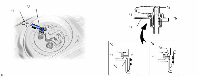
*1 Tube Joint Clip *2 Fuel Tank Main Tube Sub-assembly *3 Fuel Suction Plate Sub-assembly - - *a Fuel Tube Joint *b O-ring *c Collar *d Correct *e Incorrect - - Note
-
Check that there are no scratches or foreign matter around the connecting parts of the fuel tube joint and plug before performing this work.
-
Check that the fuel tube joint is securely inserted to the end.
-
Check that the tube joint clip is on the collar of the fuel tube joint.
-
After installing the tube joint clip, check that the fuel tank main tube sub-assembly is securely connected by pulling on it.
-
-
-
CONNECT NO. 2 FUEL EVAPORATION TUBE SUB-ASSEMBLY
-
Connect the No. 2 fuel evaporation tube sub-assembly to the fuel suction tube with pump and gauge assembly.
-
-
CONNECT NO. 1 FUEL EVAPORATION TUBE SUB-ASSEMBLY
-
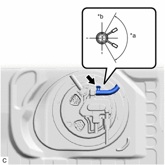
*a 120° *b Up Connect the No. 1 fuel evaporation tube sub-assembly to the fuel suction tube with pump and gauge assembly and slide the clip to secure it.
Tech Tips
Engage the clip within the area shown in the illustration.
-
-
CONNECT CHARCOAL CANISTER OUTLET TUBE SUB-ASSEMBLY
-
Connect the charcoal canister outlet tube sub-assembly to the fuel suction tube with pump and gauge assembly.
-
-
INSTALL REAR FLOOR SERVICE HOLE COVER
-
Remove any remaining butyl tape from the rear floor service hole cover and vehicle body.
-
Clean the installation surfaces of the rear floor service hole cover and vehicle body.
-
Connect the fuel pump connector.
-
Install the rear floor service hole cover with new butyl tape.
-
Return the rear floor mat assembly to its original position.
-
-
INSTALL SEAT TRACK LOWER RAIL PROTECTOR
-
CONNECT CABLE TO NEGATIVE BATTERY TERMINAL
Note
When disconnecting the cable, some systems need to be initialized after the cable is reconnected.
-
INSPECT FOR FUEL LEAK
-
PERFORM INITIALIZATION
-
Perform "Inspection After Repair" after replacing the fuel pump.
-