FUEL SENDER GAUGE ASSEMBLY REMOVAL
CAUTION / NOTICE / HINT
The necessary procedures (adjustment, calibration, initialization, or registration) that must be performed after parts are removed, installed, or replaced during the fuel sender gauge assembly removal/installation are shown below.
| Replacement Part or Procedure | Necessary Procedures | Effects/Inoperative when not Performed | Link |
|---|---|---|---|
| Battery terminal is disconnected/reconnected | Drive the vehicle until stop and start control is permitted (approximately 15 to 40 minutes) | Stop and start system | |
| Memorize steering angle neutral point | Panoramic view monitor system | ||
| Initialize back door lock | Power door lock control system | ||
| Initialize servo motor | Air conditioning system | ||
| Reset slide door close position | Power slide door system | ||
| Reset back door close position | Power back door system |
PROCEDURE
-
REMOVE FUEL SUCTION TUBE WITH PUMP AND GAUGE ASSEMBLY
-
REMOVE FUEL SENDER GAUGE ASSEMBLY
-
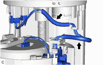
Remove the 2 harness protectors from the wire harness.
Note
Do not damage the wire harness.
-
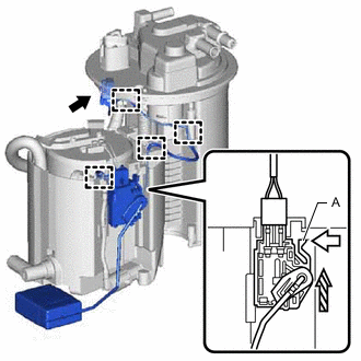

Push 
Pull up Disengage the 4 clamps to disconnect the fuel pump harness and wire harness of the fuel sender gauge assembly.
-
Disconnect the fuel sender gauge assembly connector.
-
Push the claw (A) of the fuel sender gauge assembly, and then pull up the fuel sender gauge assembly to remove it.
Note
-
Do not touch the resistance plate or contacts of the fuel sender gauge assembly.
-
Be careful not to bend the arm of the fuel sender gauge assembly.
-
-