FUEL PRESSURE PULSATION DAMPER REMOVAL

CAUTION / NOTICE / HINT
The necessary procedures (adjustment, calibration, initialization, or registration) that must be performed after parts are removed, installed, or replaced during the fuel pressure pulsation damper assembly removal/installation are shown below.
| Replacement Part or Procedure | Necessary Procedures | Effects/Inoperative when not Performed | Link |
|---|---|---|---|
| Battery terminal is disconnected/reconnected | Drive the vehicle until stop and start control is permitted (approximately 15 to 40 minutes) | Stop and start system | |
| Memorize steering angle neutral point | Panoramic view monitor system | ||
| Initialize back door lock | Power door lock control system | ||
| Initialize servo motor | Air conditioning system | ||
| Reset slide door close position | Power slide door system | ||
| Reset back door close position | Power back door system |
PROCEDURE
-
PRECAUTION
Note
After turning the engine switch off, waiting time may be required before disconnecting the cable from the negative (-) battery terminal. Therefore, make sure to read the disconnecting the cable from the negative (-) battery terminal notice before proceeding with work.
-
DISCHARGE FUEL SYSTEM PRESSURE
-
SEPARATE CENTER NO. 1 COWL TOP VENTILATOR LOUVER
-
DISCONNECT CABLE FROM NEGATIVE BATTERY TERMINAL
Note
When disconnecting the cable, some systems need to be initialized after the cable is reconnected.
-
REMOVE BATTERY
-
REMOVE AIR CLEANER CAP SUB-ASSEMBLY
-
REMOVE AIR CLEANER CASE SUB-ASSEMBLY
-
REMOVE AIR CLEANER HOSE ASSEMBLY
-
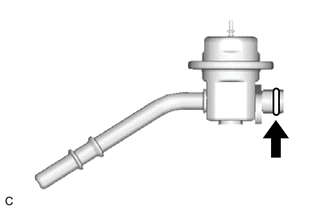
DISCONNECT FUEL TUBE SUB-ASSEMBLY
Note
Remove any foreign matter on the fuel tube connector and fuel pipe before performing this work.
-
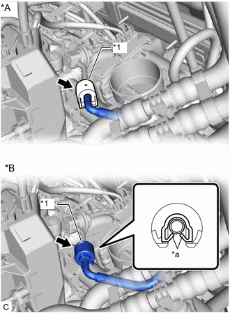
*A Type A *B Type B *1 No. 2 Fuel Pipe Clamp *a Claw Type A:
-
Remove the No. 2 fuel pipe clamp.
-
-
Type B:
-
Disengage the 2 claws to remove the No. 2 fuel pipe clamp.
Note
Do not reuse the No. 2 fuel pipe clamp.
-
-
Disconnect the fuel tube sub-assembly from the fuel delivery pipe.
-
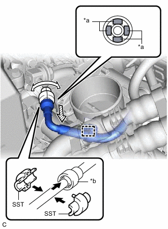
*a Retainer *b Fuel Tube Connector 
Turn 
Pull Disengage the clamp to disconnect the fuel tube sub-assembly from the fuel hose clamp.
-
Install SST (fuel hose puller) to the fuel tube connector as shown in the illustration.
- SST
- 09268-21011
-
Turn SST (fuel hose puller), align the retainers inside the fuel tube connector with the SST (fuel hose puller) chamfers and insert SST (fuel hose puller) into the fuel tube connector.
-
Mount the retainer of the fuel tube connector onto the chamfered part of SST (fuel hose puller).
-
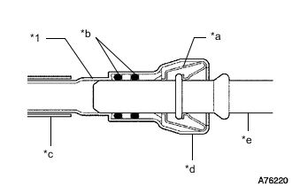
*1 Fuel Tube Sub-assembly *a Retainer *b O-ring *c Nylon Tube *d Fuel Tube Connector *e Fuel Pipe Slide SST (fuel hose puller) and the fuel tube connector together until they make a "click" sound, and then disconnect the fuel tube sub-assembly.
Note
-
Do not scratch or allow any foreign matter to get on the parts when disconnecting them as the fuel tube connector has O-rings that seal the pipe (fuel pipe).
-
Do not bend, twist, pinch or kink the nylon tube.
-
-
Check that there is no foreign matter on the sealing surfaces of the disconnected fuel lines. Clean them if necessary.
-
Cover the disconnected fuel pipe and fuel tube connector with plastic bags to prevent damage and contamination.
-
-
-
REMOVE FUEL PRESSURE PULSATION DAMPER ASSEMBLY
-
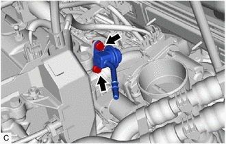
Remove the 2 bolts and fuel pressure pulsation damper assembly from the fuel delivery pipe.
-
Remove the O-ring from the fuel pressure pulsation damper assembly.
-