CYLINDER BLOCK DISASSEMBLY

PROCEDURE
-
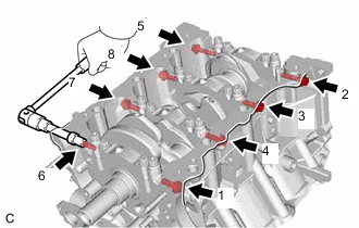
REMOVE CYLINDER BLOCK WATER JACKET SPACER
-
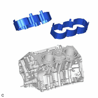
Remove the cylinder block water jacket spacer and cylinder block water jacket spacer LH from the cylinder block sub-assembly.
-
-
REMOVE PISTON SUB-ASSEMBLY WITH CONNECTING ROD
-
Check that the matchmarks on the connecting rod sub-assembly and connecting rod cap are aligned.
Tech Tips
The matchmarks on the connecting rod sub-assembly and connecting rod cap are guides for correct reassembly.
-
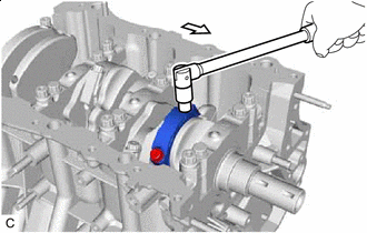

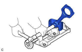
Front of Engine Remove the 2 connecting rod bolts.
-
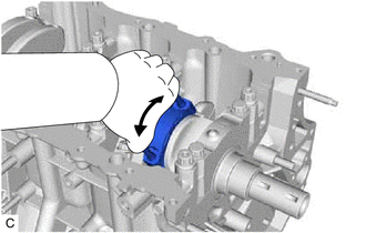
Using the 2 removed connecting rod bolts, remove the connecting rod cap and lower connecting rod bearing by wiggling the connecting rod cap right and left.
Tech Tips
Keep the lower connecting rod bearing installed to the connecting rod cap.
-
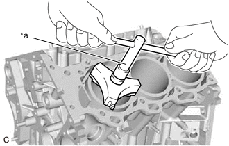
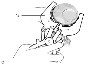
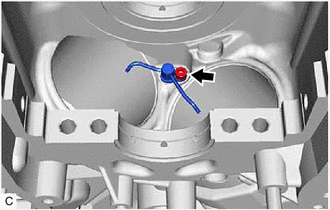
*a Ridge Reamer Using a ridge reamer, remove all of the carbon from the top of the cylinder.
-
Push the piston, connecting rod sub-assembly and upper connecting rod bearing through the top of the cylinder block sub-assembly.
Tech Tips
-
Keep the connecting rod bearing, connecting rod sub-assembly and connecting rod cap together.
-
Arrange the removed parts in such a way that they can be reinstalled to their original locations.
-
-
-
REMOVE CONNECTING ROD BEARING
-
Remove the connecting rod bearings from the connecting rod sub-assembly and connecting rod cap.
Tech Tips
Arrange the removed parts in such a way that they can be reinstalled to their original locations.
-
-
REMOVE PISTON RING SET
-
*a Piston Ring Expander Using a piston ring expander, remove the No. 1 compression ring and No. 2 compression ring.
-
Remove the oil ring expander and 2 side rails by hand.
Tech Tips
Arrange the removed parts in such a way that they can be reinstalled to their original locations.
-
-
REMOVE PISTON
-
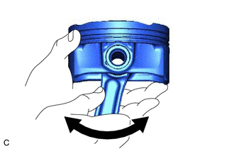
Check the fitting condition between the piston and piston pin.
-
Try to move the piston back and forth on the piston pin.
Tech Tips
If abnormal movement is felt, replace the piston and piston pin as a set.
-
-
Remove the connecting rod sub-assembly from the piston.
-
Using a screwdriver, pry out the piston pin hole snap ring (front side).
Note
-
Do not remove the piston pin hole snap ring (rear side) unless it has to be replaced.
-
Be careful not to damage the piston when removing the piston pin hole snap ring (rear side).
-
-
Gradually heat the piston to approximately 80°C (176°F).
CAUTION:
Be sure to wear protective gloves.
-
Using a brass bar and a hammer, lightly tap out the piston pin and remove the connecting rod sub-assembly.
Tech Tips
-
The piston and piston pin are a matched set.
-
Arrange the removed parts in such a way that they can be reinstalled to their original locations.
-
-
-
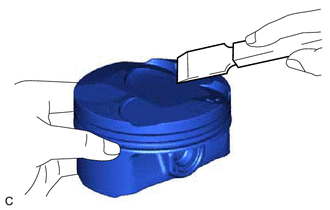
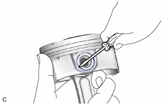
Using a gasket scraper, remove any carbon from the piston top.
Note
Be careful not to scratch the piston.
-
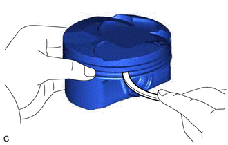
Using a groove cleaning tool or a broken ring, clean the piston ring grooves.
-
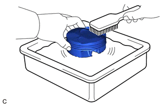
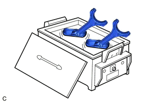
Using solvent and a brush, thoroughly clean the piston.
Note
Do not use a wire brush.
-
-
REMOVE CRANKSHAFT
-
Uniformly loosen and remove the 8 crankshaft bearing cap set bolts and 8 seal washers in several steps in the order shown in the illustration.
-
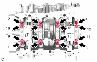
Uniformly loosen the 16 crankshaft bearing cap set bolts in several steps in the order shown in the illustration.
-
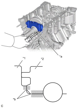
*1 Cylinder Block Sub-assembly *2 Crankshaft Bearing Cap *a Protective Tape *b Contact Surface Using a screwdriver with its tip wrapped with protective tape, pry out the 4 crankshaft bearing caps. Remove the 4 crankshaft bearing caps and 4 lower crankshaft bearings as a set.
Note
-
Push up the crankshaft bearing cap slowly and evenly, alternating between the right and left side so that the crankshaft bearing cap can be removed.
-
Be careful not to damage the contact surfaces of the cylinder block sub-assembly and the crankshaft bearing cap.
-
-
Remove the crankshaft.
-
-
REMOVE CRANKSHAFT BEARING
-
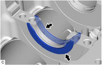
Remove the upper crankshaft bearings and lower crankshaft bearings.
Tech Tips
Arrange the removed parts in such a way that they can be reinstalled to their original locations.
-
-
REMOVE CRANKSHAFT THRUST WASHER SET
-
Remove the crankshaft thrust washer set from the cylinder block sub-assembly.
-
-
REMOVE NO. 1 OIL NOZZLE SUB-ASSEMBLY
-
Using a 5 mm hexagon socket wrench, remove the 3 bolts and 3 No. 1 oil nozzle sub-assemblies.
-
Check the 3 No. 1 oil nozzle sub-assemblies for damage or clogging.
Tech Tips
If there is damage or clogs, replace the No. 1 oil nozzle sub-assembly.
-