ENGINE ASSEMBLY INSTALLATION
CAUTION / NOTICE / HINT
CAUTION:
-
The engine assembly with transaxle is very heavy. Be sure to follow the procedure described in the repair manual, or the engine lifter may suddenly drop or the engine assembly with transaxle may fall off the engine lifter.
-
To prevent burns, do not touch the engine, exhaust manifold or other high temperature components while the engine is hot.
PROCEDURE
-
INSTALL ENGINE MOUNTING INSULATOR LH
Tech Tips
Perform this procedure only when replacement of the engine mounting insulator LH is necessary.
-
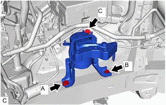
Install the engine mounting insulator LH with the 4 bolts.
- Torque:
- 95 N*m { 969 kgf*cm, 70 ft.*lbf }
Note
Temporarily tighten the bolt (A), and then fully tighten the 4 bolts in the order of (B), (C), (D) and (A).
-
Install the wire harness bracket to the engine mounting insulator LH with the bolt.
- Torque:
- 13 N*m { 133 kgf*cm, 10 ft.*lbf }
-
Connect the clamp to the wire harness bracket.
-
-
INSTALL ENGINE MOUNTING INSULATOR SUB-ASSEMBLY RH
Tech Tips
Perform this procedure only when replacement of the engine mounting insulator sub-assembly RH is necessary.
-
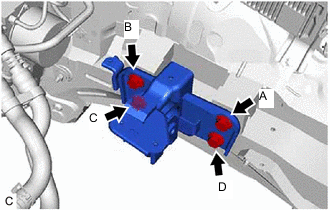
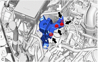
Install the engine mounting insulator sub-assembly RH with the 3 bolts.
- Torque:
- 95 N*m { 969 kgf*cm, 70 ft.*lbf }
Note
Temporarily tighten the bolt (A), and then fully tighten the 3 bolts in the order of (B), (C) and (A).
-
Install the cooler bracket to the engine mounting insulator sub-assembly RH with the nut.
- Torque:
- 9.8 N*m { 100 kgf*cm, 87 in.*lbf }
-
Connect the 4 clamps to the cooler bracket.
-
-
INSTALL ENGINE HANGERS
-
REMOVE ENGINE ASSEMBLY FROM ENGINE STAND
-
Remove the engine assembly from the engine stand.
-
-
INSTALL DRIVE PLATE AND RING GEAR SUB-ASSEMBLY
-
INSTALL AUTOMATIC TRANSAXLE ASSEMBLY
-
INSTALL STARTER ASSEMBLY
-
INSTALL DRIVE SHAFT BEARING BRACKET
-
Install the drive shaft bearing bracket with the 3 bolts.
- Torque:
- 63.7 N*m { 650 kgf*cm, 47 ft.*lbf }
-
-
INSTALL COMPRESSOR AND MAGNETIC CLUTCH
-
INSTALL GENERATOR ASSEMBLY
-
INSTALL V-RIBBED BELT
-
INSTALL MANIFOLD STAY
-
INSTALL ENGINE WIRE
-
Install the engine wire to the engine assembly.
-
-
TEMPORARILY INSTALL REAR ENGINE MOUNTING INSULATOR
Tech Tips
Perform this procedure only when replacement of the rear engine mounting insulator is necessary.
-
Temporarily install the rear engine mounting insulator to the rear engine mounting bracket with the bolt.
-
-
INSTALL FRONT ENGINE MOUNTING BRACKET
-
TEMPORARILY INSTALL FRONT ENGINE MOUNTING INSULATOR
-
Temporarily install the front engine mounting insulator to the front engine mounting bracket with the bolt and nut.
-
-
INSTALL ENGINE ASSEMBLY WITH TRANSAXLE
Tech Tips
Perform "Inspection After Repair" after replacing the engine assembly.
-
Set the engine assembly with transaxle on an engine lifter.
Note
-
Using height adjustment attachments and plate lift attachments, keep the engine assembly with transaxle horizontal.
-
Do not perform any procedures while the engine assembly is suspended because doing so may cause the engine assembly to drop, resulting in injury. However, the engine assembly needs to be suspended when it is installed to or removed from an engine stand.
-
To prevent the oil pan sub-assembly from deforming, do not place any attachments under the oil pan sub-assembly of the engine assembly with transaxle.
-
-
Remove the 4 bolts, No. 1 engine hanger and No. 2 engine hanger.
-
Operate the engine lifter and install the engine assembly with transaxle to the vehicle.
CAUTION:
Do not raise the engine assembly with transaxle more than necessary. If the engine is raised excessively, the vehicle may also be lifted up.
Note
-
Make sure that the engine assembly with transaxle is clear of all wiring and hoses.
-
While raising the engine assembly with transaxle into the vehicle, do not allow it to contact the vehicle.
-
-
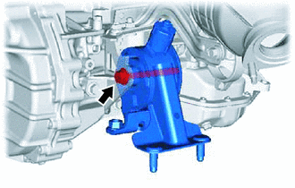
Install the engine mounting insulator LH to the engine mounting bracket LH with the bolt and nut.
- Torque:
- 56 N*m { 571 kgf*cm, 41 ft.*lbf }
Note
While holding the bolt in place, tighten the nut.
-
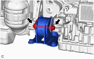
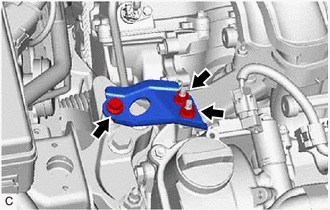
Install the engine mounting insulator sub-assembly RH to the front No. 1 engine mounting bracket LH with the 2 bolts and 2 nuts.
- Torque:
- Bolt and Nut (A)
- 95 N*m { 969 kgf*cm, 70 ft.*lbf }
- Nut (B)
- 52 N*m { 530 kgf*cm, 38 ft.*lbf }
-
Install the No. 2 engine mounting stay RH with the bolt and 2 nuts.
- Torque:
- 20 N*m { 204 kgf*cm, 15 ft.*lbf }
-
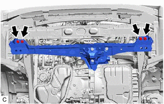
Install the front crossmember sub-assembly with the 4 bolts.
- Torque:
- 96 N*m { 979 kgf*cm, 71 ft.*lbf }
-
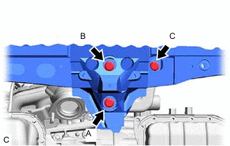
Install the front engine mounting insulator to the front crossmember sub-assembly with the 3 bolts.
- Torque:
- 95 N*m { 969 kgf*cm, 70 ft.*lbf }
Note
Temporarily tighten the bolt (A), and then fully tighten the 3 bolts in the order of (B), (C) and (A).
-
-
INSTALL FRONT SUSPENSION CROSSMEMBER SUB-ASSEMBLY
-
INSTALL FRONT SUSPENSION MEMBER BRACE SUB-ASSEMBLY LH
-
INSTALL FRONT SUSPENSION MEMBER BRACE SUB-ASSEMBLY RH
Tech Tips
Use the same procedure as for the LH side.
-
INSTALL REAR ENGINE MOUNTING INSULATOR
Tech Tips
Perform this procedure only when replacement of the rear engine mounting insulator is necessary.
-
Tighten the bolt of the rear engine mounting insulator.
- Torque:
- 95 N*m { 969 kgf*cm, 70 ft.*lbf }
-
-
INSTALL FRONT ENGINE MOUNTING INSULATOR
-
Tighten the bolt and nut of the front engine mounting insulator.
- Torque:
- 145 N*m { 1479 kgf*cm, 107 ft.*lbf }
Note
While holding the nut in place, tighten the bolt.
-
-
INSTALL DRIVE PLATE AND TORQUE CONVERTER ASSEMBLY SETTING BOLT
-
INSTALL FLYWHEEL HOUSING UNDER COVER
-
Install the flywheel housing under cover with the 2 bolts.
- Torque:
- 10 N*m { 102 kgf*cm, 7 ft.*lbf }
-
-
INSTALL FRONT SUSPENSION MEMBER REINFORCEMENT LH
-
INSTALL FRONT SUSPENSION MEMBER REINFORCEMENT RH
Tech Tips
Use the same procedure as for the LH side.
-
INSTALL FRONT DRIVE SHAFT ASSEMBLY
-
CONNECT NO. 1 STEERING COLUMN HOLE COVER SUB-ASSEMBLY
-
CONNECT NO. 2 STEERING INTERMEDIATE SHAFT ASSEMBLY
-
INSTALL COLUMN HOLE COVER SILENCER SHEET
-
CONNECT TRANSMISSION CONTROL CABLE ASSEMBLY
-
CONNECT ENGINE WIRE
-
Connect the No. 3 engine wire to the automatic transaxle assembly with the bolt and clamp.
- Torque:
- 19 N*m { 194 kgf*cm, 14 ft.*lbf }
-
Connect terminal 30 with the nut.
- Torque:
- 9.8 N*m { 100 kgf*cm, 87 in.*lbf }
-
Close the terminal cap.
-
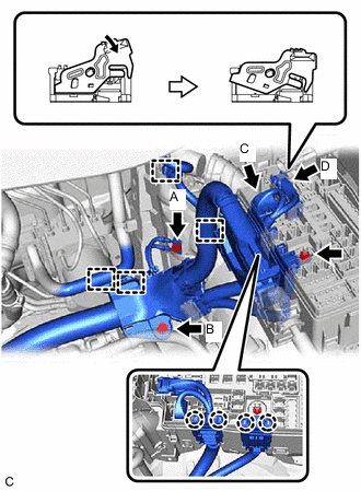
Connect the engine wire with the 2 bolts.
- Torque:
- Bolt (A)
- 8.4 N*m { 86 kgf*cm, 74 in.*lbf }
- Bolt (B)
- 13 N*m { 133 kgf*cm, 10 ft.*lbf }
-
Engage the 4 clamps.
-
Engage the 4 claws to install the engine wire to the engine room relay block assembly.
-
Install the nut to the engine room relay block assembly.
- Torque:
- 10.5 N*m { 107 kgf*cm, 8 ft.*lbf }
-
Connect the connector (C) to the engine room relay block assembly.
-
Push down the lock lever to connect (D) the connector to the engine room relay block assembly.
Note
Be sure to securely connect the connector.
-
Install the No. 1 relay block cover to the engine room relay block assembly.
-
-
CONNECT NO. 1 FUEL PIPE SUB-ASSEMBLY
-
Connect the No. 1 fuel hose (for Port Injection).
-
Connect the No. 1 fuel hose to the fuel pipe.
-
-
Connect the No. 1 fuel hose (for Direct Injection).
-
Connect the No. 1 fuel hose to the fuel pipe.
-
-
Install the No. 1 fuel pipe clamp to the fuel tube connector.
-
Engage the 2 claws to install the No. 2 fuel pipe clamp.
-
-
CONNECT UNION TO CONNECTOR TUBE HOSE
-
Connect the union to connector tube hose to the intake air surge tank assembly and slide the clip to secure it.
-
-
CONNECT NO. 1 FUEL VAPOR FEED HOSE
-
Connect the No. 1 fuel vapor feed hose to the No. 1 vacuum switching valve and slide the clip to secure it.
-
-
CONNECT HEATER HOSE
-
Connect the outlet heater water hose to the water outlet and slide the clip to secure it.
-
Connect the inlet heater water hose to the water inlet and slide the clip to secure it.
-
Engage the clamp.
-
-
CONNECT OIL COOLER ACCESSORY ASSEMBLY
-
CONNECT NO. 1 RADIATOR HOSE
-
Connect the No. 1 radiator hose to the water outlet and slide the clip to secure it.
-
Connect the air fuel ratio sensor wire to the No. 1 radiator hose with the radiator hose clamp.
-
-
INSTALL ECM
-
CONNECT NO. 2 RADIATOR HOSE
-
Connect the No. 2 radiator hose to the water inlet and slide the clip to secure it.
-
-
INSTALL RADIATOR RESERVE TANK BRACKET
-
Install the radiator reserve tank bracket with the 2 bolts.
- Torque:
- 12 N*m { 122 kgf*cm, 9 ft.*lbf }
-
-
INSTALL RADIATOR RESERVE TANK ASSEMBLY
-
Install the radiator reserve tank assembly to the radiator reserve tank bracket with the bolt.
- Torque:
- 12 N*m { 122 kgf*cm, 9 ft.*lbf }
Note
Insert the protrusion of the radiator reserve tank assembly into the grommet of the radiator reserve tank bracket.
-
-
CONNECT NO. 1 COOLER REFRIGERANT DISCHARGE HOSE
-
Remove the attached vinyl tape from the hose.
-
Apply sufficient compressor oil to a new O-ring and the fitting surface of the compressor and magnetic clutch.
Compressor oil ND-OIL 8 or equivalent -
Install the O-ring onto the No. 1 cooler refrigerant discharge hose.
-
Connect the No. 1 cooler refrigerant discharge hose with the nut.
- Torque:
- 9.8 N*m { 100 kgf*cm, 87 in.*lbf }
-
-
CONNECT NO. 1 COOLER REFRIGERANT SUCTION HOSE
-
Remove the attached vinyl tape from the hose.
-
Apply sufficient compressor oil to a new O-ring and the fitting surface of the compressor and magnetic clutch.
Compressor oil ND-OIL 8 or equivalent -
Install the O-ring onto the No. 1 cooler refrigerant suction hose.
-
Connect the No. 1 cooler refrigerant suction hose with the nut.
- Torque:
- 9.8 N*m { 100 kgf*cm, 87 in.*lbf }
-
Connect the clamp.
-
-
INSTALL OUTER COWL TOP PANEL SUB-ASSEMBLY
-
INSTALL EXHAUST MANIFOLD
-
INSTALL OIL COOLER HOSE
-
CONNECT CABLE TO NEGATIVE BATTERY TERMINAL
-
Connect the outlet oil cooler hose and inlet oil cooler hose and slide the 2 clips to secure them.
-
-
ADD ENGINE OIL
-
ADD ENGINE COOLANT
-
ADD AUTOMATIC TRANSAXLE FLUID
-
CHARGE AIR CONDITIONING SYSTEM WITH REFRIGERANT
-
WARM UP ENGINE
-
INSPECT SHIFT LEVER POSITION
-
ADJUST SHIFT LEVER POSITION
-
INSPECT FOR ENGINE OIL LEAK
-
INSPECT FOR COOLANT LEAK
-
INSPECT FOR REFRIGERANT LEAK
-
INSPECT FOR FUEL LEAK
-
INSPECT FOR EXHAUST GAS LEAK
-
CHECK ENGINE OIL LEVEL
-
INSPECT ENGINE COOLANT LEVEL IN RESERVOIR TANK
-
INSTALL REAR ENGINE UNDER COVER RH
-
Install the rear engine under cover RH with the 5 clips.
-
-
INSTALL REAR ENGINE UNDER COVER LH
-
Install the rear engine under cover LH with the 5 clips.
-
-
INSTALL NO. 2 ENGINE UNDER COVER
-
Install the No. 2 engine under cover with the 5 clips.
-
-
INSTALL NO. 1 ENGINE UNDER COVER
-
Install the No. 1 engine under cover with the 2 bolts and 5 clips.
-
-
INSTALL FRONT LOWER BUMPER ABSORBER
-
INSTALL FRONT BUMPER COVER
-
INSTALL V-BANK COVER SUB-ASSEMBLY
-
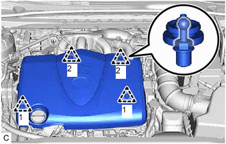
Engage the 4 clips in the order shown in the illustration to install the V-bank cover sub-assembly.
Note
-
Make sure that the clips are engaged securely.
-
Do not subject the clips to shock or apply excessive force to the clips when engaging them or they may be damaged.
-
If the clips are not engaged in the order shown in the illustration, the V-bank cover sub-assembly may be damaged.
-
-
-
INSTALL FRONT WHEELS
-
ALIGN FRONT WHEELS FACING STRAIGHT AHEAD
-
INSPECT AND ADJUST FRONT WHEEL ALIGNMENT
-
PERFORM INITIALIZATION
-
INSPECT IGNITION TIMING
-
INSPECT ENGINE IDLE SPEED
-
INSPECT CO/HC
-
CHECK FOR SPEED SENSOR SIGNAL