ENGINE ASSEMBLY REMOVAL
PROCEDURE
-
PRECAUTION
Note
After turning the engine switch off, waiting time may be required before disconnecting the cable from the negative (-) battery terminal. Therefore, make sure to read the disconnecting the cable from the negative (-) battery terminal notices before proceeding with work.
-
RECOVER REFRIGERANT FROM REFRIGERATION SYSTEM
-
DISCHARGE FUEL SYSTEM PRESSURE
-
DISCONNECT CABLE FROM NEGATIVE BATTERY TERMINAL
Note
When disconnecting the cable, some systems need to be initialized after the cable is reconnected.
-
ALIGN FRONT WHEELS FACING STRAIGHT AHEAD
-
SECURE STEERING WHEEL
-
REMOVE V-BANK COVER SUB-ASSEMBLY
-
Disengage the 4 clips in the order shown in the illustration and lift the V-bank cover sub-assembly upward to remove it.
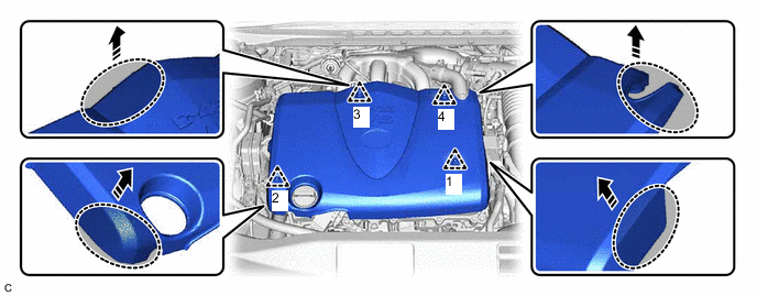

Hold here 
Pull in this Direction Note
-
Pull the V-bank cover sub-assembly straight up to remove it.
-
Do not remove the V-bank cover sub-assembly in any direction other than upward. If the V-bank cover sub-assembly is removed in any direction other than upward, it may be damaged.
-
If the clips are not disengaged in the order shown in the illustration, the V-bank cover sub-assembly may be damaged.
-
-
-
ALIGN FRONT WHEELS FACING STRAIGHT AHEAD
-
SECURE STEERING WHEEL
-
REMOVE FRONT WHEELS
-
REMOVE FRONT BUMPER COVER
-
REMOVE FRONT LOWER BUMPER ABSORBER
-
REMOVE NO. 1 ENGINE UNDER COVER
-
Remove the 2 bolts, 5 clips and No. 1 engine under cover.
-
-
REMOVE NO. 2 ENGINE UNDER COVER
-
Remove the 5 clips and No. 2 engine under cover.
-
-
REMOVE REAR ENGINE UNDER COVER LH
-
Remove the 5 clips and rear engine under cover LH.
-
-
REMOVE REAR ENGINE UNDER COVER RH
-
Remove the 5 clips and rear engine under cover RH.
-
-
DRAIN ENGINE COOLANT
-
DRAIN ENGINE OIL
-
DRAIN AUTOMATIC TRANSAXLE FLUID
-
DISCONNECT OIL COOLER HOSE
-
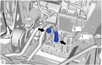
*1 Inlet Oil Cooler Hose *2 Outlet Oil Cooler Hose Slide the 2 clips and disconnect the inlet oil cooler hose and outlet oil cooler hose from the automatic transaxle assembly.
-
-
REMOVE EXHAUST MANIFOLD
-
REMOVE OUTER COWL TOP PANEL SUB-ASSEMBLY
-
DISCONNECT NO. 1 COOLER REFRIGERANT SUCTION HOSE
-
Disconnect the clamp.
-
Remove the nut and disconnect the No. 1 cooler refrigerant suction hose.
Note
Seal the openings of the disconnected parts using vinyl tape to prevent entry of moisture and foreign matter.
-
-
DISCONNECT NO. 1 COOLER REFRIGERANT DISCHARGE HOSE
-
Remove the nut and disconnect the No. 1 cooler refrigerant discharge hose.
Note
Seal the openings of the disconnected parts using vinyl tape to prevent entry of moisture and foreign matter.
-
-
REMOVE RADIATOR RESERVE TANK ASSEMBLY
-
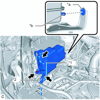
*1 No. 1 Water By-pass Hose *2 No. 2 Water By-pass Hose *a Grommet *b Protrusion Slide the 2 clips and disconnect the No. 1 water by-pass hose and No. 2 water by-pass hose from the radiator reserve tank assembly.
-
Remove the bolt and radiator reserve tank assembly from the radiator reserve tank bracket.
-
-
REMOVE RADIATOR RESERVE TANK BRACKET
-
Remove the 2 bolts and radiator reserve tank bracket.
-
-
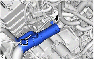
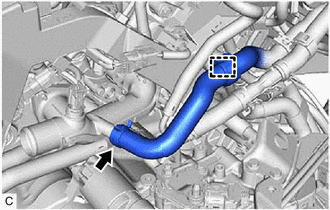
DISCONNECT NO. 2 RADIATOR HOSE
-
Slide the clip and disconnect the No. 2 radiator hose from the water inlet.
-
-
REMOVE ECM
-
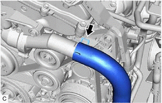
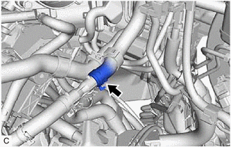
DISCONNECT NO. 1 RADIATOR HOSE
-
Remove the radiator hose clamp to disconnect the air fuel ratio sensor wire from the No. 1 radiator hose.
-
Slide the clip and disconnect the No. 1 radiator hose from the water outlet.
-
-
DISCONNECT OIL COOLER ACCESSORY ASSEMBLY
-
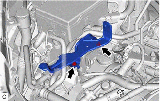
DISCONNECT HEATER HOSE
-
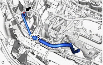
Disengage the clamp.
-
Slide the clip and disconnect the inlet heater water hose from the water outlet.
-
Slide the clip and disconnect the outlet heater water hose from the heater water pipe.
-
-
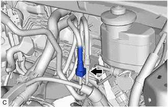
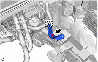
DISCONNECT NO. 1 FUEL VAPOR FEED HOSE
-
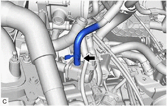
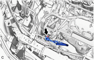
Slide the clip and disconnect the No. 1 fuel vapor feed hose from the No. 1 vacuum switching valve assembly.
-
-
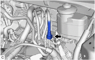
DISCONNECT UNION TO CONNECTOR TUBE HOSE
-
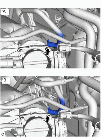
*A for LHD *B for RHD Slide the clip and disconnect the union to connector tube hose from the intake air surge tank assembly.
-
-
DISCONNECT NO. 1 FUEL PIPE SUB-ASSEMBLY
-
Disengage the 2 claws to remove the No. 2 fuel pipe clamp.
-
Remove the No. 1 fuel pipe clamp from the fuel tube connector.
-
Disconnect the No. 1 fuel hose (for Port Injection).
-
Disconnect the No. 1 fuel hose from the fuel pipe.
-
-
Disconnect the No. 1 fuel hose (for Direct Injection).
-
Disconnect the No. 1 fuel hose from the fuel pipe.
-
-
-
DISCONNECT ENGINE WIRE
Tech Tips
After disconnecting the wire harness, secure it with tape or equivalent to keep it out of the way.
-
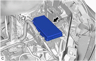
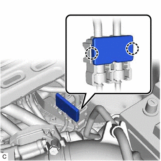
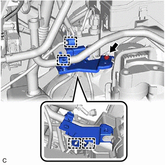
Remove the No. 1 relay block cover from the engine room relay block assembly.
-
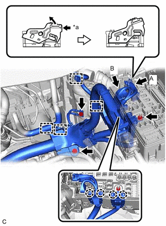
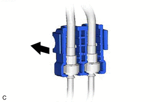
*a Push Pull up the lock lever and disconnect the connector (A).
-
Disconnect the connector (B) from the engine room relay block assembly.
-
Remove the nut from the engine room relay block assembly.
-
Using a screwdriver, disengage the 4 claws and separate the engine wire from the engine room relay block assembly.
-
Disengage the 4 clamps.
-
Remove the 2 bolts to disconnect the engine wire.
-
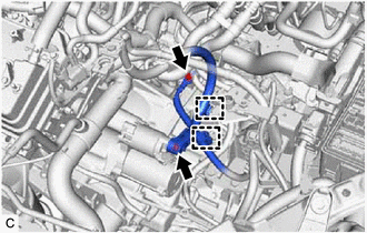
Open the terminal cap.
-
Remove the nut and disconnect terminal 30.
-
Remove the bolt and clamp and disconnect the No. 3 engine wire from the automatic transaxle assembly.
-
-
DISCONNECT TRANSMISSION CONTROL CABLE ASSEMBLY
-
REMOVE COLUMN HOLE COVER SILENCER SHEET
-
DISCONNECT NO. 2 STEERING INTERMEDIATE SHAFT ASSEMBLY
-
DISCONNECT NO. 1 STEERING COLUMN HOLE COVER SUB-ASSEMBLY
-
REMOVE FRONT DRIVE SHAFT ASSEMBLY
-
REMOVE FRONT SUSPENSION MEMBER REINFORCEMENT LH
-
REMOVE FRONT SUSPENSION MEMBER REINFORCEMENT RH
-
REMOVE FLYWHEEL HOUSING UNDER COVER
-
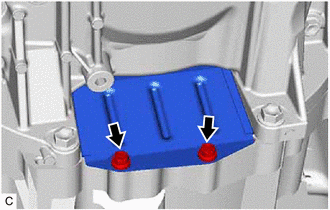
Remove the 2 bolts and flywheel housing under cover.
-
-
REMOVE DRIVE PLATE AND TORQUE CONVERTER ASSEMBLY SETTING BOLT
-
REMOVE FRONT SUSPENSION MEMBER BRACE SUB-ASSEMBLY LH
-
REMOVE FRONT SUSPENSION MEMBER BRACE SUB-ASSEMBLY RH
Tech Tips
Use the same procedure as for the LH side.
-
REMOVE FRONT SUSPENSION CROSSMEMBER SUB-ASSEMBLY
-
REMOVE ENGINE ASSEMBLY WITH TRANSAXLE
-
Set the engine assembly with transaxle on an engine lifter.
Note
-
Using height adjustment attachments and plate lift attachments, keep the engine assembly with transaxle horizontal.
-
Do not position the height adjustment attachments or plate lift attachments under the front cross member sub-assembly.
-
Do not perform any procedures while the engine assembly is suspended because doing so may cause the engine assembly to drop, resulting in injury. However, the engine assembly needs to be suspended when it is installed to or removed from an engine stand.
-
To prevent the engine assembly from unexpectedly moving, securely support the engine assembly until it is secured to an engine stand.
-
To prevent the oil pan sub-assembly from deforming, do not place any attachments under the oil pan sub-assembly of the engine assembly with transaxle.
-
-
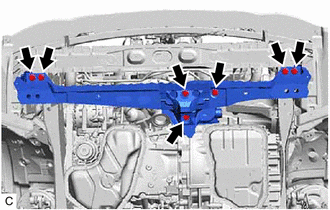
Remove the 7 bolts and front crossmember sub-assembly.
-
Remove the bolt, 2 nuts and No. 2 engine mounting stay RH.
-
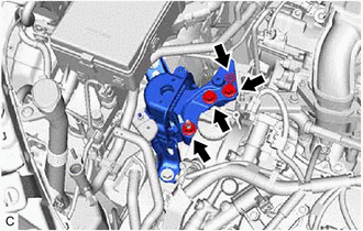
Remove the 2 bolts and 2 nuts and separate the engine mounting insulator sub-assembly RH from the Front No. 1 engine mounting bracket LH.
-
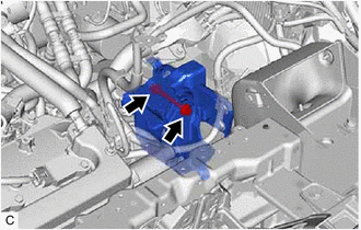
Remove the bolt and nut and separate the engine mounting insulator LH from the engine mounting bracket LH.
-
Operate the engine lifter and remove the engine assembly with transaxle from the vehicle.
Note
-
Make sure that the engine assembly with transaxle is clear of all wiring and hoses.
-
While lowering the engine assembly with transaxle from the vehicle, do not allow it to contact the vehicle.
-
-
-
INSTALL ENGINE HANGERS
-
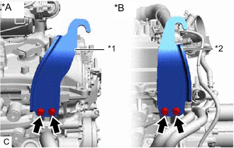
*A for Bank 1 *B for Bank 2 *1 No. 1 Engine Hanger *2 No. 2 Engine Hanger Install the No. 1 engine hanger and No. 2 engine hanger with the 4 bolts as shown in the illustration.
- Torque:
- 33 N*m { 337 kgf*cm, 24 ft.*lbf }
Tech Tips
No. 1 Engine Hanger 12281-31121 No. 2 Engine Hanger 12282-31100 Bolt 91671-10825 -
Using an engine sling device and engine lifter, secure the engine assembly with transaxle.
Note
-
Adjust the angle of the sling device carefully to prevent damage or deformation to the engine hangers or engine assembly.
-
Do not perform any procedures while the engine assembly is suspended because doing so may cause the engine assembly to drop, resulting in injury. However, the engine assembly needs to be suspended when it is installed to or removed from an engine stand.
-
-
-
REMOVE FRONT ENGINE MOUNTING INSULATOR
-
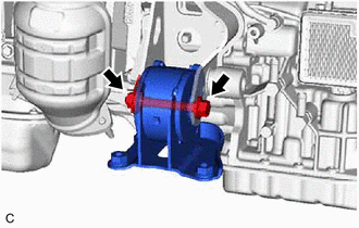
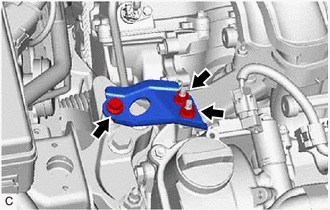
Remove the bolt, nut and front engine mounting insulator from the front engine mounting bracket.
Note
While holding the nut in place, loosen the bolt.
-
-
REMOVE FRONT ENGINE MOUNTING BRACKET
-
REMOVE REAR ENGINE MOUNTING INSULATOR
Tech Tips
Perform this procedure only when replacement of the rear engine mounting insulator is necessary.
-
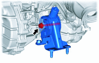
Remove the bolt and rear engine mounting insulator from the rear engine mounting bracket.
-
-
REMOVE ENGINE WIRE
-
Disconnect all clamps and connectors and remove the engine wire from the engine assembly with transaxle.
-
-
REMOVE MANIFOLD STAY
-
REMOVE V-RIBBED BELT
-
REMOVE GENERATOR ASSEMBLY
-
REMOVE COMPRESSOR AND MAGNETIC CLUTCH
-
REMOVE DRIVE SHAFT BEARING BRACKET
-
Remove the 3 bolts and drive shaft bearing bracket.
-
-
REMOVE STARTER ASSEMBLY
-
REMOVE AUTOMATIC TRANSAXLE ASSEMBLY
-
REMOVE DRIVE PLATE AND RING GEAR SUB-ASSEMBLY
-
INSTALL ENGINE ASSEMBLY TO ENGINE STAND
-
Install the engine assembly to an engine stand.
-
-
REMOVE ENGINE HANGERS
-
Remove the 4 bolts, No. 1 engine hanger and No. 2 engine hanger from the cylinder head sub-assembly and cylinder head LH.
-
-
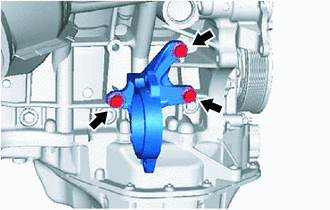
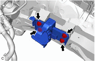
REMOVE ENGINE MOUNTING INSULATOR SUB-ASSEMBLY RH
Tech Tips
Perform this procedure only when replacement of the engine mounting insulator sub-assembly RH is necessary.
-
Disconnect the 4 clamps from the cooler bracket.
-
Remove the nut and cooler bracket from the engine mounting insulator sub-assembly RH.
-
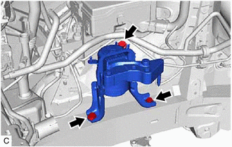
Remove the 3 bolts and engine mounting insulator sub-assembly RH.
-
-
REMOVE ENGINE MOUNTING INSULATOR LH
Tech Tips
Perform this procedure only when replacement of the engine mounting insulator LH is necessary.
-
Disconnect the clamp from the wire harness bracket.
-
Remove the bolt and wire harness bracket from the engine mounting insulator LH.
-
Remove the 4 bolts and engine mounting insulator LH.
-