CYLINDER HEAD GASKET INSTALLATION
PROCEDURE
-
INSTALL NO. 2 CYLINDER HEAD GASKET
-
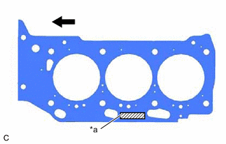
*a Lot No. 
Front of Engine Place a new No. 2 cylinder head gasket on the cylinder block sub-assembly as shown in the illustration.
Note
-
Remove any oil from the contact surfaces.
-
Make sure to install the No. 2 cylinder head gasket in the correct direction.
-
-
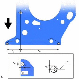
*1 No. 2 Cylinder Head Gasket *a 5.0 to 7.0 mm (0.197 to 0.276 in.) *b 3.0 to 5.0 mm (0.118 to 0.197 in.) *c 7.0 to 9.0 mm (0.276 to 0.354 in.) *d 38.2 mm (1.50 in.) *e 110.0 mm (4.33 in.) Front of Engine 
Seal Packing Apply seal packing to the No. 2 cylinder head gasket as shown in the illustration.
Seal Packing Toyota Genuine Seal Packing Black, Three Bond 1207B or equivalent Note
-
Remove any oil from the contact surfaces.
-
Install the No. 2 cylinder head gasket within 3 minutes and tighten the cylinder head set bolts within 15 minutes of applying seal packing.
-
-
-
INSTALL CYLINDER HEAD LH
-
INSTALL CYLINDER HEAD GASKET
-
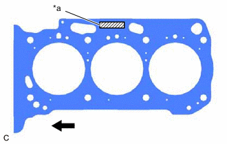
*a Lot No. Front of Engine Place a new cylinder head gasket on the cylinder block sub-assembly as shown in the illustration.
Note
-
Remove any oil from the contact surfaces.
-
Make sure to install the cylinder head gasket in the correct direction.
-
-
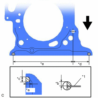
*1 Cylinder Head Gasket *a 5.0 to 7.0 mm (0.197 to 0.276 in.) *b 3.0 to 5.0 mm (0.118 to 0.197 in.) *c 7.0 to 9.0 mm (0.276 to 0.354 in.) *d 38.5 mm (1.52 in.) *e 144.0 mm (5.67 in.) Front of Engine Seal Packing Apply seal packing to the cylinder head gasket as shown in the illustration.
Seal Packing Toyota Genuine Seal Packing Black, Three Bond 1207B or equivalent Note
-
Remove any oil from the contact surfaces.
-
Install the cylinder head gasket within 3 minutes and tighten the cylinder head set bolts within 15 minutes of applying seal packing.
-
-
-
INSTALL CYLINDER HEAD SUB-ASSEMBLY
-
INSTALL WATER OUTLET
-
INSTALL VALVE STEM CAP
-
INSTALL VALVE LASH ADJUSTER ASSEMBLY
-
INSTALL NO. 1 VALVE ROCKER ARM SUB-ASSEMBLY
-
INSTALL NO. 1 CHAIN VIBRATION DAMPER
-
INSTALL NO. 2 CHAIN VIBRATION DAMPER
-
INSTALL SENSOR WIRE
-
INSTALL NO. 3 CAMSHAFT SUB-ASSEMBLY
-
INSTALL NO. 4 CAMSHAFT SUB-ASSEMBLY
-
INSTALL CAMSHAFT BEARING CAP (for Bank 2)
-
SET CAMSHAFT TIMING GEAR ASSEMBLY, CAMSHAFT TIMING EXHAUST GEAR ASSEMBLY AND NO. 2 CHAIN SUB-ASSEMBLY (for Bank 2)
-
TEMPORARILY INSTALL CAMSHAFT TIMING GEAR BOLT (for Intake Side of Bank 2)
-
TEMPORARILY INSTALL CAMSHAFT TIMING GEAR BOLT (for Exhaust Side of Bank 2)
-
INSTALL CAMSHAFT HOUSING SUB-ASSEMBLY LH
-
TIGHTEN CAMSHAFT TIMING GEAR BOLT (for Intake Side of Bank 2)
-
TIGHTEN CAMSHAFT TIMING GEAR BOLT (for Exhaust Side of Bank 2)
-
INSTALL CAMSHAFT SUB-ASSEMBLY
-
INSTALL NO. 2 CAMSHAFT
-
INSTALL CAMSHAFT BEARING CAP (for Bank 1)
-
SET CAMSHAFT TIMING GEAR ASSEMBLY, CAMSHAFT TIMING EXHAUST GEAR ASSEMBLY AND NO. 2 CHAIN SUB-ASSEMBLY (for Bank 1)
-
TEMPORARILY INSTALL CAMSHAFT TIMING GEAR BOLT (for Intake Side of Bank 1)
-
TEMPORARILY INSTALL CAMSHAFT TIMING GEAR BOLT (for Exhaust Side of Bank 1)
-
INSTALL CAMSHAFT HOUSING SUB-ASSEMBLY
-
TIGHTEN CAMSHAFT TIMING GEAR BOLT (for Intake Side of Bank 1)
-
TIGHTEN CAMSHAFT TIMING GEAR BOLT (for Exhaust Side of Bank 1)
-
INSTALL NO. 3 CHAIN TENSIONER ASSEMBLY
-
INSTALL NO. 2 CHAIN TENSIONER ASSEMBLY
-
INSTALL CHAIN SUB-ASSEMBLY
-
INSTALL CHAIN TENSIONER SLIPPER
-
INSTALL NO. 1 CHAIN TENSIONER ASSEMBLY
-
INSPECT VALVE TIMING
-
INSTALL TIMING CHAIN COVER ASSEMBLY
-
INSTALL TIMING CHAIN CASE OIL SEAL
-
INSTALL OIL PAN SUB-ASSEMBLY
-
Install 2 new oil pan gaskets to the timing chain cover assembly.
-
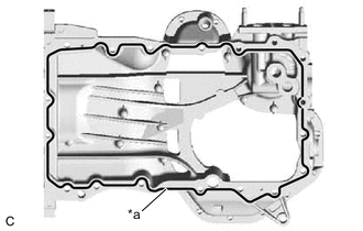
*a Seal Packing Apply seal packing in a continuous line as shown in the illustration.
Seal Packing Toyota Genuine Seal Packing Black, Three Bond 1207B or equivalent Seal Packing Diameter 3.0 to 4.0 mm (0.118 to 0.157 in.) Note
-
Remove any oil from the contact surfaces.
-
Install the oil pan sub-assembly within 3 minutes of applying seal packing.
-
Do not start the engine for at least 2 hours after installation.
-
-
Install the oil pan sub-assembly with the 16 bolts and 2 nuts in the order shown in the illustration.
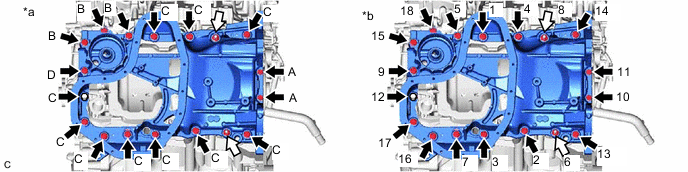
*a Torque *b Bolt and Nut Tightening Order Bolt 
Nut - Torque:
- Bolt (A)
- 10 N*m { 102 kgf*cm, 7 ft.*lbf }
- Bolt (B), (C), (D)
- 21 N*m { 214 kgf*cm, 15 ft.*lbf }
- Nut
- 21 N*m { 214 kgf*cm, 15 ft.*lbf }
Bolt Length Item Length Bolt (A) 16 mm (0.630 in.) Bolt (B) 45 mm (1.77 in.) Bolt (C) 25 mm (0.984 in.) Bolt (D) 70 mm (2.76 in.) -
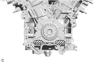
Wipe off the Seal Packing Wipe off any excess seal packing with a clean piece of cloth.
Note
Do not allow seal packing to contact the No. 1 crankshaft position sensor plate.
-
-
INSTALL OIL STRAINER SUB-ASSEMBLY
-
INSTALL NO. 2 OIL PAN SUB-ASSEMBLY
-
INSTALL SPARK PLUG TUBE GASKET
-
INSTALL CYLINDER HEAD COVER SUB-ASSEMBLY LH
-
INSTALL CYLINDER HEAD COVER SUB-ASSEMBLY
-
INSTALL SENSOR WIRE
-
INSTALL CRANKSHAFT POSITION SENSOR PROTECTOR
-
INSTALL CAMSHAFT TIMING OIL CONTROL SOLENOID ASSEMBLY (for Intake Side of Bank 2)
-
INSTALL CAMSHAFT TIMING OIL CONTROL SOLENOID ASSEMBLY (for Exhaust Side of Bank 2)
-
INSTALL CAMSHAFT TIMING OIL CONTROL SOLENOID ASSEMBLY (for Exhaust Side of Bank 1)
-
INSTALL CAMSHAFT TIMING OIL CONTROL SOLENOID ASSEMBLY (for Intake Side of Bank 1)
-
INSTALL WATER INLET WITH THERMOSTAT SUB-ASSEMBLY
-
CONNECT NO. 1 WATER BY-PASS HOSE
-
INSTALL ENGINE MOUNTING BRACKET RH
-
INSTALL CRANKSHAFT PULLEY
-
INSTALL WIRE HARNESS CLAMP BRACKET
-
INSTALL ENGINE OIL LEVEL DIPSTICK GUIDE
-
INSTALL WATER PUMP PULLEY
-
INSTALL V-RIBBED BELT TENSIONER ASSEMBLY
-
INSTALL NO. 2 IDLER PULLEY SUB-ASSEMBLY
-
INSTALL COMPRESSOR ASSEMBLY WITH MAGNETIC CLUTCH
-
INSTALL GENERATOR ASSEMBLY
-
INSTALL V-RIBBED BELT
-
INSTALL VACUUM PUMP ASSEMBLY
-
INSTALL IGNITION COIL ASSEMBLY
-
INSTALL KNOCK CONTROL SENSOR
-
INSTALL ENGINE HANGERS
-
REMOVE ENGINE ASSEMBLY FROM ENGINE STAND