CYLINDER HEAD DISASSEMBLY

CAUTION / NOTICE / HINT
The necessary procedures (adjustment, calibration, initialization, or registration) that must be performed after parts are removed, installed, or replaced during the engine unit removal/installation are shown below.
| Replacement Part or Procedure | Necessary Procedures | Effects/Inoperative when not Performed | Link |
|---|---|---|---|
| Battery terminal is disconnected/reconnected | Memorize steering angle neutral point | Panoramic view monitor system | |
| Initialize back door lock | Power door lock control system | ||
| Initialize servo motor | Air conditioning system | ||
| Reset slide door close position | Power slide door system | ||
| Reset back door close position | Power back door system | ||
| Replacement of ECM | Perform Vehicle Identification Number (VIN) or frame number registration |
|
|
| ECU Communication ID Registration (Immobiliser system) | Engine start function | See Service Bulletin for the registration method. | |
| Perform code registration (Immobiliser system) |
|
See Service Bulletin for the registration method. | |
|
Inspection After Repair |
|
|
| Replacement of automatic transaxle assembly | Perform the following procedures in the order shown:
|
|
Click here for Initialization Click here for Registration |
| Front wheel alignment adjustment |
|
|
|
| Work that changes the vehicle height such as replacement or removal/installation of the rear height control sensor sub-assembly LH or replacement of suspension components | Initialize headlight light control ECU sub-assembly LH | Headlight leveling function | |
| Removal/installtaion of the radiator grille | Television camera view adjustment | Panoramic view monitor system |
PROCEDURE
-
REMOVE INTAKE VALVE
-
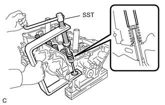
Using SST, compress the inner compression spring and remove the valve spring retainer lock.
- SST
- 09202-70020 ( 09202-01010, 09202-01020 )
- 09202-00020
-
Remove the valve spring retainer, inner compression spring and intake valve from the cylinder head sub-assembly.
Tech Tips
Arrange the removed parts in such away that they can be reinstalled to their original locations.
-
-
REMOVE EXHAUST VALVE
-
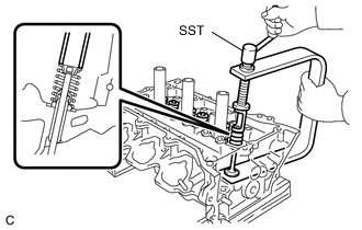
Using SST, compress the inner compression spring and remove the valve spring retainer lock.
- SST
- 09202-70020 ( 09202-01010, 09202-01020 )
- 09202-00020
-
Remove the valve spring retainer, inner compression spring and exhaust valve from the cylinder head sub-assembly.
Tech Tips
Arrange the removed parts in such away that they can be reinstalled to their original locations.
-
-
REMOVE INTAKE VALVE STEM OIL SEAL
-
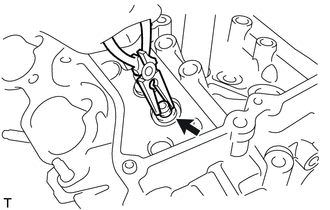
Using needle-nose pliers, remove the intake valve stem oil seal.
-
-
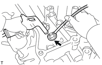
REMOVE EXHAUST VALVE STEM OIL SEAL
-
Using needle-nose pliers, remove the exhaust valve stem oil seal.
-
-
REMOVE VALVE SPRING SEAT
-
Using compressed air and a magnet hand, remove the valve spring seat by blowing air onto them.
-
-
REMOVE NO. 1 STRAIGHT SCREW PLUG
Note
If coolant leaks from a No. 1 straight screw plug or a plug is corroded, replace it.
-
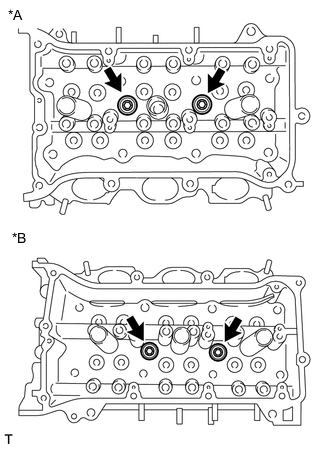
*A for Bank 1 *B for Bank 2 Using a 10 mm hexagon wrench, remove the 4 No. 1 straight screw plugs and 4 gaskets.
-
-
REMOVE NO. 2 STRAIGHT SCREW PLUG
Note
If coolant leaks from a No. 2 straight screw plug or a plug is corroded, replace it.
-
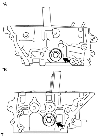
*A for Bank 1 *B for Bank 2 Using a 14 mm hexagon wrench, remove the 2 No. 2 straight screw plugs and 2 gaskets.
-