CAMSHAFT REMOVAL
PROCEDURE
-
INSTALL ENGINE ASSEMBLY TO ENGINE STAND
-
REMOVE ENGINE HANGERS
-
REMOVE THROTTLE BODY WITH MOTOR ASSEMBLY
-
DISCONNECT VENTILATION HOSE
-
DISCONNECT PURGE VALVE (PURGE VSV)
-
REMOVE NO. 2 SURGE TANK STAY
-
REMOVE INTAKE AIR SURGE TANK ASSEMBLY
-
REMOVE AIR SURGE TANK TO INTAKE MANIFOLD GASKET
-
REMOVE IGNITION COIL ASSEMBLY
-
REMOVE VACUUM PUMP ASSEMBLY
-
REMOVE ENGINE OIL LEVEL DIPSTICK GUIDE
-
REMOVE WIRE HARNESS CLAMP BRACKET
-

Remove the bolt and wire harness clamp bracket from the camshaft housing sub-assembly LH.
-
Remove the bolt and wire harness clamp bracket from the camshaft housing sub-assembly.
-
-
REMOVE CAMSHAFT TIMING OIL CONTROL SOLENOID ASSEMBLY (for Intake Side of Bank 1)
-
REMOVE CAMSHAFT TIMING OIL CONTROL SOLENOID ASSEMBLY (for Exhaust Side of Bank 1)
-
REMOVE CAMSHAFT TIMING OIL CONTROL SOLENOID ASSEMBLY (for Exhaust Side of Bank 2)
-
REMOVE CAMSHAFT TIMING OIL CONTROL SOLENOID ASSEMBLY (for Intake Side of Bank 2)
-
REMOVE VVT SENSOR (for Intake Side of Bank 1)
-
REMOVE VVT SENSOR (for Exhaust Side of Bank 1)
-
REMOVE VVT SENSOR (for Intake Side of Bank 2)
-
REMOVE VVT SENSOR (for Exhaust Side of Bank 2)
-
REMOVE CYLINDER HEAD COVER SUB-ASSEMBLY
-
REMOVE CYLINDER HEAD COVER SUB-ASSEMBLY LH
-
REMOVE SPARK PLUG TUBE GASKET
-
REMOVE TIMING CHAIN COVER PLATE
-
SET NO. 1 CYLINDER TO TDC (COMPRESSION)
-
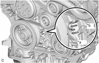
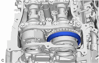
*a Timing Mark (Cutout) *b "0" Timing Mark Turn the crankshaft clockwise to align the timing mark (cutout) on the crankshaft pulley with the "0" timing mark on the timing chain cover assembly.
-
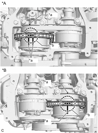
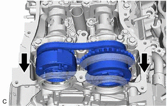
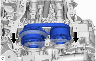
*A for Bank 2 *B for Bank 1 *a Timing Mark *b Paint Mark Check that the timing marks of the camshaft timing gear assemblies are aligned with the timing marks of the camshaft bearing caps as shown in the illustration.
Tech Tips
If the marks are not aligned, turn the crankshaft again to align the marks.
-
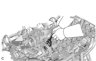
Place paint marks on the timing marks and sprockets of each camshaft timing gear assembly and on the links of the chain sub-assembly.
Tech Tips
Be sure to place the paint marks on 2 links of the chain sub-assembly and on the sprockets of the camshaft timing gear assemblies at the locations of the timing marks of the camshaft timing gear assemblies.
-
-
REMOVE NO. 1 CHAIN TENSIONER ASSEMBLY
-
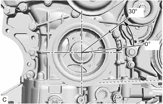
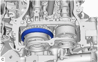
Turn the crankshaft approximately 30° counterclockwise so that there is some slack in the chain sub-assembly.
Tech Tips
This prevents the valves and pistons from interfering with each other.
-
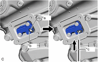
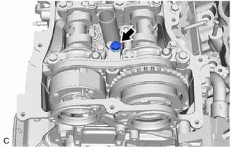
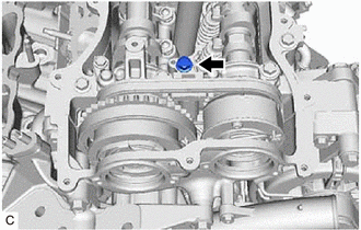
*a Lever Hole *b Tensioner Body *c Pin Align the hole in the lever of the No. 1 chain tensioner assembly with the hole in the tensioner body as shown in the illustration, and then insert a pin with a diameter of 1.0 mm (0.0394 in.) into the hole.
Note
Check that the pin is locked.
-
*a Timing Mark (Cutout) *b "0" Timing Mark Turn the crankshaft clockwise to align the timing mark (cutout) on the crankshaft pulley with the "0" timing mark on the timing chain cover assembly.
-
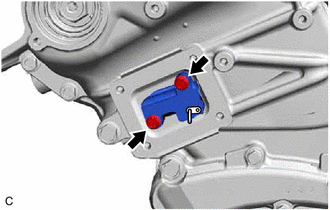
Remove the 2 bolts and No. 1 chain tensioner assembly from the cylinder head sub-assembly.
Note
Do not drop the No. 1 chain tensioner assembly or bolts into the timing chain cover assembly.
-
-
DISCONNECT CHAIN SUB-ASSEMBLY (for Bank 1)
-
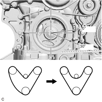
Turn the crankshaft clockwise until it is in the position shown in the illustration so that there is some slack in the chain sub-assembly between the banks.
CAUTION:
As the camshafts may turn suddenly, do not touch the camshafts or camshaft timing gears.
Tech Tips
When turning the crankshaft, engine oil may spray out of the oil holes.
-
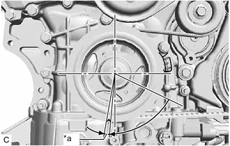
*a 5 to 10° Turn the crankshaft clockwise until it is in the position shown in the illustration so that the chain sub-assembly can be removed easily.
Tech Tips
When turning the crankshaft, engine oil may spray out of the oil holes.
-
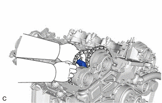
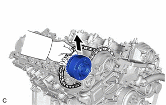
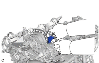
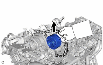
Remove the chain sub-assembly from the sprocket of the camshaft timing gear assembly and set it on the camshaft timing gear assembly.
CAUTION:
As the camshaft may turn suddenly and pinch your fingers when the chain sub-assembly is removed, pinch the chain sub-assembly and lift it upward to remove it from the sprocket.
-
-
SEPARATE NO. 2 CHAIN TENSIONER ASSEMBLY
-
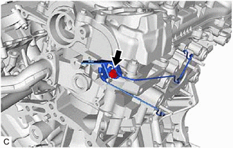
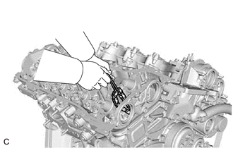
Remove the bolt to separate the No. 2 chain tensioner assembly from the camshaft housing sub-assembly.
-
-
REMOVE CAMSHAFT TIMING GEAR BOLT (for Intake Side of Bank 1)
-
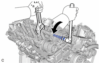
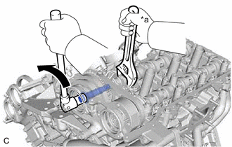
*a Hold 
Turn Use a wrench to hold the hexagonal portion of the camshaft sub-assembly and remove the camshaft timing gear bolt from the camshaft timing gear assembly.
Note
-
Be careful not to damage the camshaft sub-assembly, camshaft housing sub-assembly or spark plug tube with the wrench.
-
If the camshaft timing gear bolt has been struck or dropped, replace it.
-
-
-
REMOVE CAMSHAFT TIMING GEAR BOLT (for Exhaust Side of Bank 1)
-
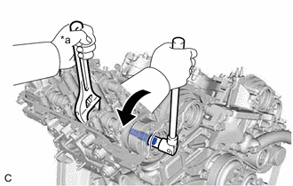
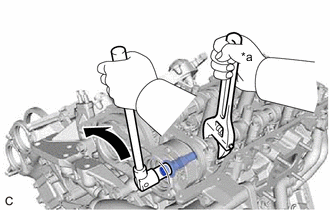
*a Hold Turn Use a wrench to hold the hexagonal portion of the No. 2 camshaft and remove the camshaft timing gear bolt from the camshaft timing exhaust gear assembly.
Note
-
Be careful not to damage the No. 2 camshaft, camshaft housing sub-assembly or spark plug tube with the wrench.
-
If the camshaft timing gear bolt has been struck or dropped, replace it.
-
-
-
REMOVE CAMSHAFT BEARING CAP (for Bank 1)
-
Slide the camshaft timing gear assembly and camshaft timing exhaust gear assembly as shown in the illustration.
-
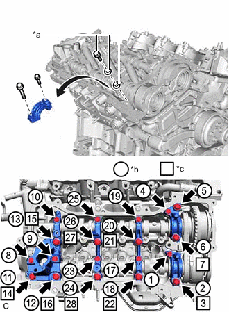
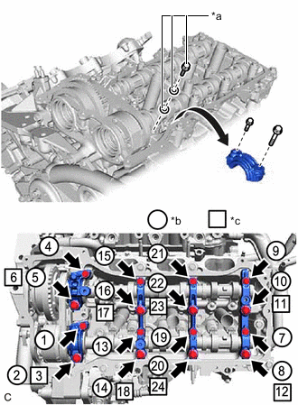
*a Replacement Bolt and Washer *b Part Removal *c Replacement Bolt and Washer Installation Remove the bolts and camshaft bearing caps in the order shown in the illustration. Immediately after removing a camshaft bearing cap, install replacement bolts and washers in the order shown in the illustration.
- Torque:
- 10 N*m { 102 kgf*cm, 7 ft.*lbf }
Note
-
Do not install the camshaft bearing caps when installing replacement bolts and washers.
-
Be sure to follow the numerical order when performing this procedure.
-
Do not allow replacement bolts or washers to contact the camshaft.
-
Do not drop replacement bolts or washers into the cylinder head sub-assembly.
Tech Tips
-
Arrange the removed parts so that they can be reinstalled in their original locations.
-
Part number for replacement bolts: 91551-F0850 (9 bolts)
-
Part number for replacement washers: 90201-12028 (18 washers)
-
-
REMOVE NO. 2 CAMSHAFT
-
While lifting up the camshaft timing exhaust gear assembly, remove the No. 2 chain tensioner assembly.
-
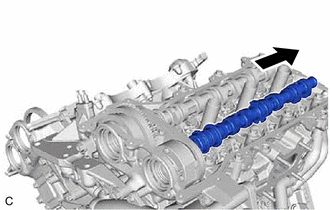
Lift up the rear of the No. 2 camshaft so that it is at an angle.
-
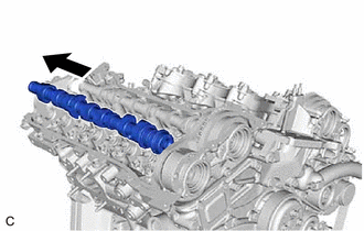
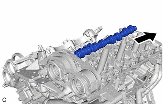
Pull the No. 2 camshaft as shown in the illustration to remove it from the camshaft timing exhaust gear assembly.
-
-
REMOVE CAMSHAFT SUB-ASSEMBLY
-
Lift up the rear of the camshaft sub-assembly so that it is at an angle.
-
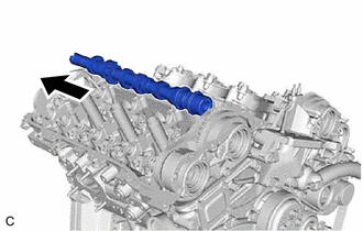
Pull the camshaft sub-assembly as shown in the illustration to remove it from the camshaft timing gear assembly.
-
-
REMOVE CAMSHAFT TIMING EXHAUST GEAR ASSEMBLY (for Bank 1)
-
Remove the camshaft timing exhaust gear assembly.
-
-
REMOVE CAMSHAFT TIMING GEAR ASSEMBLY (for Bank 1)
-
Remove the camshaft timing gear assembly and No. 2 chain sub-assembly.
Note
Do not drop the chain sub-assembly into the gap between the engine and timing chain cover assembly.
-
Suspend the chain sub-assembly with a string or equivalent.
-
-
DISCONNECT CHAIN SUB-ASSEMBLY (for Bank 2)
-
*a Timing Mark (Cutout) *b "0" Timing Mark Turn the crankshaft counterclockwise to align the timing mark (cutout) on the crankshaft pulley with the "0" timing mark on the timing chain cover assembly.
-
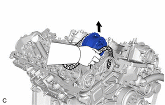
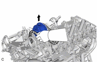
Remove the chain sub-assembly from the sprocket of the camshaft timing gear assembly and set it on the camshaft timing gear assembly.
CAUTION:
As the camshaft may turn suddenly and pinch your fingers when the chain sub-assembly is removed, pinch the chain sub-assembly and lift it upward to remove it from the sprocket.
-
-
SEPARATE NO. 3 CHAIN TENSIONER ASSEMBLY
-
Remove the bolt to separate the No. 3 chain tensioner assembly from the camshaft housing sub-assembly LH.
-
-
REMOVE CAMSHAFT TIMING GEAR BOLT (for Intake Side of Bank 2)
-
*a Hold Turn Use a wrench to hold the hexagonal portion of the No. 3 camshaft sub-assembly and remove the camshaft timing gear bolt from the camshaft timing gear assembly.
Note
-
Be careful not to damage the No. 3 camshaft sub-assembly, camshaft housing sub-assembly LH or spark plug tube with the wrench.
-
If the camshaft timing gear bolt has been struck or dropped, replace it.
-
-
-
REMOVE CAMSHAFT TIMING GEAR BOLT (for Exhaust Side of Bank 2)
-
*a Hold Turn Use a wrench to hold the hexagonal portion of the No. 4 camshaft sub-assembly and remove the camshaft timing gear bolt from the camshaft timing exhaust gear assembly.
Note
-
Be careful not to damage the No. 4 camshaft sub-assembly, camshaft housing sub-assembly LH or spark plug tube with the wrench.
-
If the camshaft timing gear bolt has been struck or dropped, replace it.
-
-
-
REMOVE CAMSHAFT BEARING CAP (for Bank 2)
-
Slide the camshaft timing gear assembly and camshaft timing exhaust gear assembly as shown in the illustration.
-
*a Replacement Bolt and Washer *b Part Removal *c Replacement Bolt and Washer Installation Remove the bolts and camshaft bearing caps in the order shown in the illustration. Immediately after removing a camshaft bearing cap, install replacement bolts and washers in the order shown in the illustration.
- Torque:
- 10 N*m { 102 kgf*cm, 7 ft.*lbf }
Note
-
Do not install the camshaft bearing caps when installing replacement bolts and washers.
-
Be sure to follow the numerical order when performing this procedure.
-
Do not allow replacement bolts or washers to contact the camshaft.
-
Do not drop replacement bolts or washers into the cylinder head LH.
Tech Tips
-
Arrange the removed parts so that they can be reinstalled in their original locations.
-
Part number for replacement bolts: 91551-F0850 (8 bolts)
-
Part number for replacement washers: 90201-12028 (16 washers)
-
-
REMOVE NO. 4 CAMSHAFT SUB-ASSEMBLY
-
While lifting up the camshaft timing exhaust gear assembly, remove the No. 3 chain tensioner assembly.
-
Lift up the rear of the No. 4 camshaft sub-assembly so that it is at an angle.
-
Pull the No. 4 camshaft sub-assembly as shown in the illustration to remove it from the camshaft timing exhaust gear assembly.
-
-
REMOVE NO. 3 CAMSHAFT SUB-ASSEMBLY
-
Lift up the rear of the No. 3 camshaft sub-assembly so that it is at an angle.
-
Pull the No. 3 camshaft sub-assembly as shown in the illustration to remove it from the camshaft timing gear assembly.
-
-
REMOVE CAMSHAFT TIMING EXHAUST GEAR ASSEMBLY (for Bank 2)
-
Remove the camshaft timing exhaust gear assembly.
-
-
REMOVE CAMSHAFT TIMING GEAR ASSEMBLY (for Bank 2)
-
Remove the camshaft timing gear assembly and No. 2 chain sub-assembly.
Note
Do not drop the chain sub-assembly into the gap between the engine and timing chain cover assembly.
-
Suspend the chain sub-assembly with a string or equivalent.
-