ENGINE UNIT REASSEMBLY

PROCEDURE
-
INSTALL REAR ENGINE OIL SEAL
-
Place the rear engine oil seal retainer on wooden blocks.
-
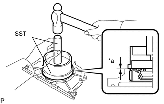
*a Depth Using SST, tap in a new rear engine oil seal until its surface is flush with the rear engine oil seal retainer edge.
- SST
- 09223-15030
- 09950-70010 ( 09951-07100 )
Note
-
Keep the lip free from foreign matter.
-
Do not tap in the engine rear oil seal at an angle.
-
-
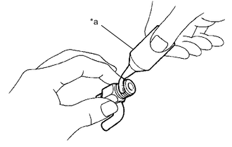
INSTALL REAR ENGINE OIL SEAL RETAINER
-
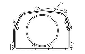
*a Seal Packing Apply seal packing in a continuous line as shown in the illustration.
Seal Packing Toyota Genuine Seal Packing Black, Three Bond 1207B or equivalent Seal Packing Diameter 2.0 to 3.0 mm (0.0787 to 0.118 in.) Note
-
Remove any oil from the contact surfaces.
-
Install the rear engine oil seal retainer within 3 minutes of applying seal packing.
-
Do not start the engine for at least 2 hours after installation.
-
-
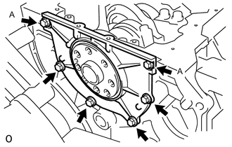
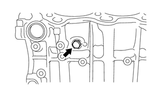
Install the rear engine oil seal retainer with the 6 bolts.
- Torque:
- 10 N*m { 102 kgf*cm, 7 ft.*lbf }
Note
Be sure to apply adhesive to the bolts (A) before installing them.
Adhesive Toyota Genuine Adhesive 1324, Three Bond 1324 or equivalent
-
-
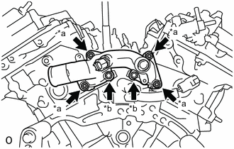
INSTALL WATER INLET PIPE
-
Install the water inlet pipe with the 2 bolts.
- Torque:
- 10 N*m { 102 kgf*cm, 7 ft.*lbf }
-
Connect the No. 1 water by-pass hose to the water inlet pipe and slide the clip to secure it.
-
-
INSTALL CYLINDER HEAD GASKET
-
INSTALL CYLINDER HEAD SUB-ASSEMBLY
-
Place the cylinder head sub-assembly onto the cylinder block sub-assembly.
Note
-
Do not allow oil to adhere to the bottom of the cylinder head sub-assembly.
-
Gently lower the cylinder head sub-assembly in order not to damage the gasket with the bottom of the cylinder head sub-assembly.
Tech Tips
The cylinder head set bolts are tightened in 3 progressive steps.
-
-
Apply a light coat of engine oil to the threads and under the heads of the cylinder head set bolts.
-
Step 1:
-
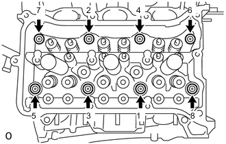
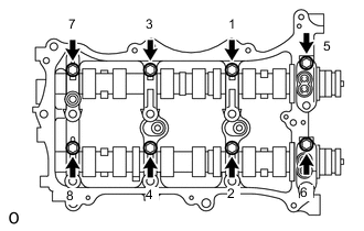
Using a 10 mm bi-hexagon wrench, install and uniformly tighten the 8 cylinder head set bolts with plate washers in several steps in the order shown in the illustration.
- Torque:
- 36 N*m { 367 kgf*cm, 27 ft.*lbf }
-
-
Step 2:
-
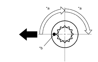
*a Turn 90° *b Paint Mark 
Front of Engine Mark each cylinder head set bolt head with paint as shown in the illustration.
-
Tighten the cylinder head set bolts 90° in the order shown in step 1.
-
-
Step 3:
-
Tighten the cylinder head set bolts an additional 90° in the order shown in step 1.
-
Check that the paint marks are now facing rearward.
Tech Tips
Perform Inspection After Repair after replacing the cylinder head sub-assembly.
-
-
-
INSTALL NO. 2 CYLINDER HEAD GASKET
-
INSTALL CYLINDER HEAD LH
-
Place the cylinder head LH onto the cylinder block sub-assembly.
Note
-
Do not allow oil to adhere to the bottom of the cylinder head LH.
-
Gently lower the cylinder head LH in order not to damage the gasket with the bottom of the cylinder head LH.
Tech Tips
The cylinder head set bolts are tightened in 3 progressive steps.
-
-
Apply a light coat of engine oil to the threads and under the heads of the cylinder head set bolts.
-
Step 1:
-
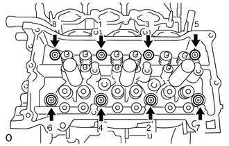
Using a 10 mm bi-hexagon wrench, install and uniformly tighten the 8 cylinder head set bolts with plate washers in several steps in the order shown in the illustration.
- Torque:
- 36 N*m { 367 kgf*cm, 27 ft.*lbf }
-
-
Step 2:
-
*a Turn 90° *b Paint Mark Front of Engine Mark each cylinder head set bolt head with paint as shown in the illustration.
-
Tighten the cylinder head set bolts 90° in the order shown in step 1.
-
-
Step 3:
-
Tighten the cylinder head set bolts an additional 90° in the order shown in step 1.
-
Check that the paint marks are now facing rearward.
-
-
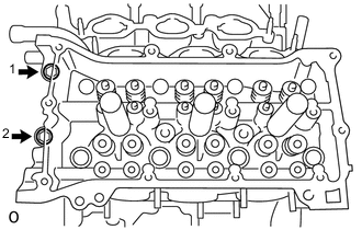
Tighten the 2 bolts in the order shown in the illustration.
- Torque:
- 30 N*m { 306 kgf*cm, 22 ft.*lbf }
-
-
INSTALL VALVE STEM CAP
-
Install the 24 valve stem caps.
-
-
INSTALL VALVE LASH ADJUSTER ASSEMBLY
-
Inspect the valve lash adjuster assembly.
-
Install the 24 valve lash adjuster assemblies to the cylinder head sub-assembly.
-
-
INSTALL NO. 1 VALVE ROCKER ARM SUB-ASSEMBLY
-
Apply engine oil to the valve lash adjuster assembly tip and valve stem cap end.
-
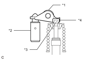
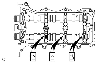
*1 No. 1 Valve Rocker Arm Sub-assembly *2 Valve Lash Adjuster Assembly *3 Valve Stem *4 Valve Stem Cap Install the 24 No. 1 valve rocker arm sub-assemblies as shown in the illustration.
-
-
INSTALL CAMSHAFT
-
INSTALL NO. 2 CAMSHAFT
-
INSTALL CAMSHAFT BEARING CAP (for Bank 1)
-
Apply engine oil to the 5 camshaft bearing caps.
-
Confirm the marks and numbers on the camshaft bearing caps and place them in their proper positions and directions.
-
Temporarily tighten the 8 bolts in the order shown in the illustration.
- Torque:
- 10 N*m { 102 kgf*cm, 7 ft.*lbf }
-
-
INSTALL CAMSHAFT HOUSING SUB-ASSEMBLY RH
-
*1 No. 1 Valve Rocker Arm Sub-assembly *2 Valve Lash Adjuster Assembly *3 Valve Stem *4 Valve Stem Cap Make sure that the No. 1 valve rocker arm sub-assemblies are installed as shown in the illustration.
-
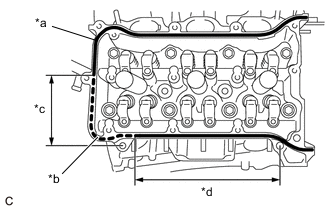
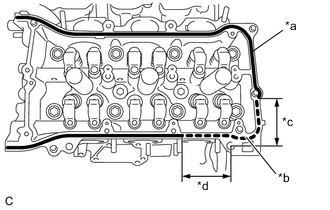
*a Continuous Line Area (Seal Packing) *b Dashed line area (Seal Packing) *c 118 mm (4.65 in.) *d 232 mm (9.13 in.) Apply seal packing in a continuous line as shown in the illustration.
Seal Packing Toyota Genuine Seal Packing Black, Three Bond 1207B or equivalent Seal Packing Application Specification Area Seal Packing Diameter Continuous Line Area 2.7 to 4.5 mm (0.107 to 0.177 in.) Dashed Line Area 3.5 to 4.5 mm (0.138 to 0.177 in.) Note
-
Remove any oil from the contact surface.
-
Install the camshaft housing sub-assembly RH and tighten the bolts within 3 minutes.
-
Do not start the engine for at least 2 hours after installation.
-
-
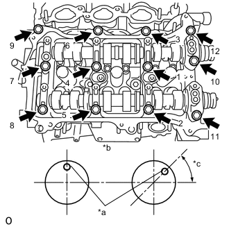
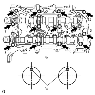
*a Knock Pin *b Front View *c 45° Install the camshaft housing sub-assembly RH and tighten the 12 bolts in the order shown in the illustration.
- Torque:
- 28 N*m { 286 kgf*cm, 21 ft.*lbf }
Note
-
When installing the camshaft housing sub-assembly RH, correctly position the camshafts as shown in the illustration.
Failure to do so may result in damage due to contact between the pistons and valves. If a camshaft is rotated, valve contact with a piston at TDC may occur.
-
If any of the bolts are loosened during installation, remove the camshaft housing sub-assembly RH, clean the installation surfaces, and reapply seal packing.
-
If the camshaft housing sub-assembly RH is removed because any of the bolts are loosened during installation, make sure that the previously applied seal packing does not enter any oil passages.
-
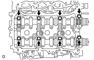
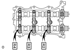
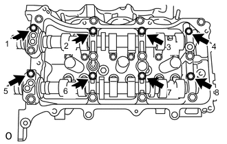
Tighten the 8 bolts in the order shown in the illustration.
- Torque:
- 16 N*m { 163 kgf*cm, 12 ft.*lbf }
-
-
INSTALL NO. 3 CAMSHAFT SUB-ASSEMBLY
-
INSTALL NO. 4 CAMSHAFT SUB-ASSEMBLY
-
INSTALL CAMSHAFT BEARING CAP (for Bank 2)
-
Apply engine oil to the 5 camshaft bearing caps.
-
Confirm the marks and numbers on the camshaft bearing caps and place them in each proper position and direction.
-
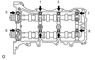
Temporarily tighten the 8 bolts in the order shown in the illustration.
- Torque:
- 10 N*m { 102 kgf*cm, 7 ft.*lbf }
-
-
INSTALL CAMSHAFT HOUSING SUB-ASSEMBLY LH
-
*1 No. 1 Valve Rocker Arm Sub-assembly *2 Valve Lash Adjuster Assembly *3 Valve Stem *4 Valve Stem Cap Make sure that the No. 1 valve rocker arm sub-assemblies are installed as shown in the illustration.
-
*a Continuous Line Area (Seal Packing) *b Dashed line area (Seal Packing) *c 63 mm (2.48 in.) *d 79 mm (3.11 in.) Apply seal packing in a continuous line as shown in the illustration.
Seal Packing Toyota Genuine Seal Packing Black, Three Bond 1207B or equivalent Seal Packing Application Specification Area Seal Packing Diameter Continuous Line Area 2.7 to 4.5 mm (0.107 to 0.177 in.) Dashed Line Area 3.5 to 4.5 mm (0.138 to 0.177 in.) Note
-
Remove any oil from the contact surface.
-
Install the camshaft housing sub-assembly LH and tighten the bolts within 3 minutes.
-
Do not start the engine for at least 2 hours after installation.
-
-
*a Knock Pin *b Front View Install the camshaft housing sub-assembly LH and tighten the 13 bolts in the order shown in the illustration.
- Torque:
- 28 N*m { 286 kgf*cm, 21 ft.*lbf }
Note
-
When installing the camshaft housing sub-assembly LH, correctly position the camshafts as shown in the illustration. Failure to do so may result in damage due to contact between the pistons and valves. If a camshaft is rotated, valve contact with a piston at TDC may occur.
-
If any of the bolts are loosened during installation, remove the camshaft housing sub-assembly LH, clean the installation surfaces, and reapply seal packing.
-
If the camshaft housing sub-assembly LH is removed because any of the bolts are loosened during installation, make sure that the previously applied seal packing does not enter any oil passages.
-
Tighten the 8 bolts in the order shown in the illustration.
- Torque:
- 16 N*m { 163 kgf*cm, 12 ft.*lbf }
-
-
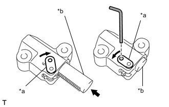
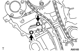
INSTALL NO. 2 CHAIN TENSIONER ASSEMBLY
-
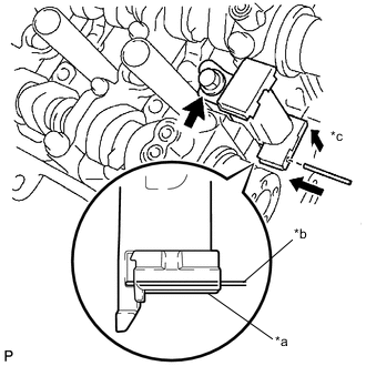
*a Plunger *b Pin *c Push Install the No. 2 chain tensioner assembly with the bolt.
- Torque:
- 21 N*m { 214 kgf*cm, 15 ft.*lbf }
-
While pushing up the No. 2 chain tensioner assembly, insert a 1.0 mm (0.0394 in.) diameter pin into the hole to secure it.
-
-
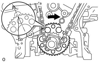
INSTALL CAMSHAFT TIMING GEAR ASSEMBLY, CAMSHAFT TIMING EXHAUST GEAR ASSEMBLY AND NO. 2 CHAIN SUB-ASSEMBLY (for Bank 1)
-
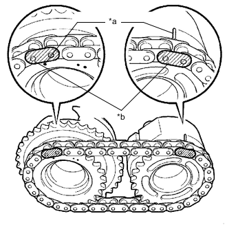
*a Timing Mark *b Mark Plate Align the mark plates (yellow) with the timing marks of the camshaft timing gear assembly as shown in the illustration.
-
Apply a light coat of engine oil to the bolt threads and bolt-seating surfaces.
-
Align the knock pins of the camshaft and No. 2 camshaft with the pin holes of the camshaft timing gear assembly and camshaft timing exhaust gear assembly. Install the camshaft timing gear assembly and camshaft timing exhaust gear assembly with the No. 2 chain sub-assembly installed.
-
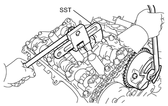
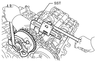
Using SST to hold the hexagonal portion of each camshaft, tighten the bolts of the camshaft timing gear assembly and camshaft timing exhaust gear assembly.
- SST
- 09922-10010
- Torque:
- 100 N*m { 1020 kgf*cm, 74 ft.*lbf }
-
Remove the pin from the No. 2 chain tensioner assembly.
Tech Tips
Perform Inspection After Repair after replacing the camshaft timing gear assembly or camshaft timing exhaust gear assembly.
-
-
INSTALL NO. 3 CHAIN TENSIONER ASSEMBLY
-
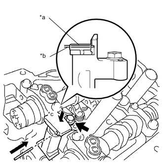
*a Plunger *b Pin *c Push Install the No. 3 chain tensioner assembly with the bolt.
- Torque:
- 21 N*m { 214 kgf*cm, 15 ft.*lbf }
-
While pushing down the No. 3 chain tensioner assembly, insert a 1.0 mm (0.0394 in.) diameter pin into the hole to secure it.
-
-
INSTALL CAMSHAFT TIMING GEAR ASSEMBLY, CAMSHAFT TIMING EXHAUST GEAR ASSEMBLY AND NO. 2 CHAIN SUB-ASSEMBLY (for Bank 2)
-
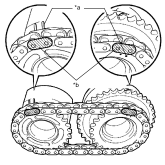
*a Timing Mark *b Mark Plate Align the mark plates (yellow) with the timing marks of the camshaft timing gear assembly as shown in the illustration.
-
Apply a light coat of engine oil to the bolt threads and bolt-seating surfaces.
-
Align the knock pins of the No. 3 camshaft and No. 4 camshaft with the pin holes of the camshaft timing gear assembly and camshaft timing exhaust gear assembly. Install the camshaft timing gear assembly and camshaft timing exhaust gear assembly with the No. 2 chain sub-assembly installed.
-
Using SST to hold the hexagonal portion of each camshaft, tighten the bolts of the camshaft timing gear assembly and camshaft timing exhaust gear assembly.
- SST
- 09922-10010
- Torque:
- 100 N*m { 1020 kgf*cm, 74 ft.*lbf }
-
Remove the pin from the No. 3 chain tensioner assembly.
Tech Tips
Perform Inspection After Repair after replacing the camshaft timing gear assembly or camshaft timing exhaust gear assembly.
-
-
INSTALL NO. 1 CHAIN VIBRATION DAMPER
-
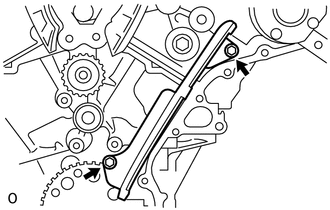
Install the No. 1 chain vibration damper with the 2 bolts.
- Torque:
- 22.5 N*m { 229 kgf*cm, 17 ft.*lbf }
-
-
INSTALL NO. 2 CHAIN VIBRATION DAMPER
-
Install the 2 No. 2 chain vibration dampers.
-
-
INSTALL CRANKSHAFT TIMING SPROCKET
-
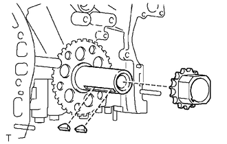
Install the 2 pulley set keys and crankshaft timing sprocket as shown in the illustration.
-
-
INSTALL IDLE SPROCKET ASSEMBLY
-
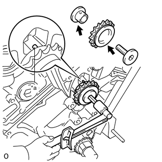
*a Knock Pin Light coat of engine oil Apply a light coat of engine oil to the rotating surface of the No. 1 idle gear shaft.
-
Temporarily install the No. 1 idle gear shaft and idle sprocket assembly with the No. 2 idle gear shaft while aligning the knock pin of the No. 1 idle gear shaft with the pin hole of the cylinder block sub-assembly.
Note
Make sure to install the No. 1 idle gear shaft installation in the correct direction.
Tech Tips
Check that there is no foreign matter on the No. 1 idle gear shaft or No. 2 idle gear shaft.
-
Using a 10 mm hexagon wrench, tighten the No. 2 idle gear shaft.
- Torque:
- 60 N*m { 612 kgf*cm, 44 ft.*lbf }
Tech Tips
After installing the idle sprocket assembly, check that the idle sprocket assembly turns smoothly.
-
-
INSTALL CHAIN SUB-ASSEMBLY
-
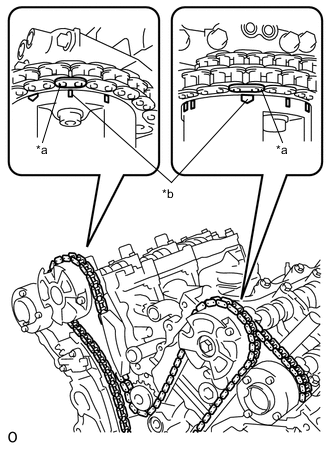
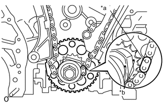
*a Mark Plate *b Timing Mark Align the mark plates and timing marks as shown in the illustration and install the chain sub-assembly.
Tech Tips
The camshaft mark plates are orange.
-
Temporarily place the chain sub-assembly on the crankshaft as shown in the illustration.
-
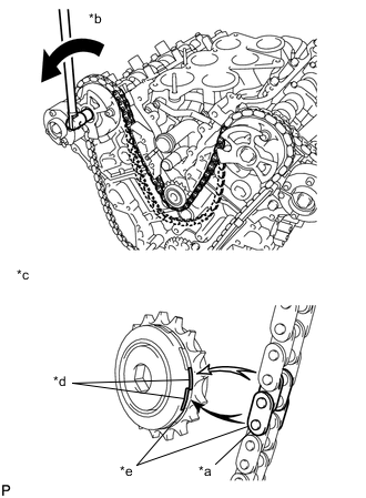
*a Mark Plate *b Turn *c When the idle sprocket assembly is reused *d Mark *e Align Turn the camshaft timing gear assembly on bank 1 counterclockwise to tighten the chain sub-assembly between the banks.
Note
When reusing the idle sprocket assembly, align the mark plate with the mark where the mark plate had been in order to tighten the chain sub-assembly between the banks.
-
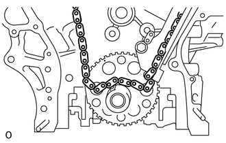
*a Mark Plate *b Timing Mark Align the mark plate and timing marks as shown in the illustration and install the chain sub-assembly around the crankshaft timing sprocket.
Tech Tips
The crankshaft mark plate is yellow.
-
Temporarily tighten the crankshaft pulley bolt.
-
*a Center Line *b Timing Mark *c Sensor Plate Turn the crankshaft clockwise to set it to the center of the block bore (for Bank 1) (TDC/compression).
-
-
INSTALL CHAIN TENSIONER SLIPPER
-
Install the chain tensioner slipper.
-
-
INSTALL NO. 1 CHAIN TENSIONER ASSEMBLY
-
*a Stopper Plate *b Plunger Turn the stopper plate clockwise to release the lock, and push the plunger deep into the No. 1 chain tensioner assembly.
-
Turn the stopper plate counterclockwise to set the lock, and insert a hexagon wrench into the hole of the stopper plate.
-
Install the No. 1 chain tensioner assembly with the 2 bolts.
- Torque:
- 10 N*m { 102 kgf*cm, 7 ft.*lbf }
-
Remove the hexagon wrench from the No. 1 chain tensioner assembly.
-
-
INSPECT VALVE TIMING
-
INSTALL TIMING CHAIN CASE OIL SEAL
-
INSTALL TIMING CHAIN COVER PLATE
-
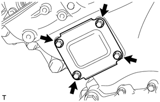
Install a new gasket and the timing chain cover plate with the 4 bolts.
- Torque:
- 9.1 N*m { 93 kgf*cm, 81 in.*lbf }
-
-
INSTALL ENGINE WATER PUMP ASSEMBLY
-
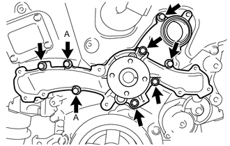
Install a new water pump gasket and the engine water pump assembly with the 8 bolts.
- Torque:
- 11 N*m { 112 kgf*cm, 8 ft.*lbf }
Note
Replace the bolts (A) with new ones, or make sure to apply adhesive 1344 if reusing the bolts.
Adhesive Toyota Genuine Adhesive 1344, Three Bond 1344 or equivalent
-
-
INSTALL TIMING CHAIN COVER SUB-ASSEMBLY
-
INSTALL WATER INLET HOUSING
-
Install the water inlet housing.
-
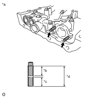
*a 9 mm (0.354 in.) *b 25 mm (0.984 in.) Install the 2 stud bolts.
- Torque:
- 4.0 N*m { 41 kgf*cm, 35 in.*lbf }
-
-
INSTALL DRAIN COCK ASSEMBLY
-
Install the drain cock assembly to the water inlet housing.
- Torque:
- 30 N*m { 306 kgf*cm, 22 ft.*lbf }
-
-
INSTALL THERMOSTAT
-
INSTALL WATER INLET
-
INSTALL NO. 1 OIL PAN BAFFLE PLATE
-
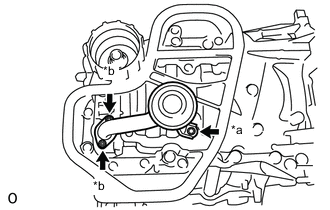
Install the No. 1 oil pan baffle plate with the 7 bolts.
- Torque:
- 10 N*m { 102 kgf*cm, 7 ft.*lbf }
Tech Tips
Temporarily tighten the 7 bolts. Fully tighten the 2 bolts (A) shown in the illustration before tightening the other bolts.
-
-
INSTALL OIL PAN SUB-ASSEMBLY
-
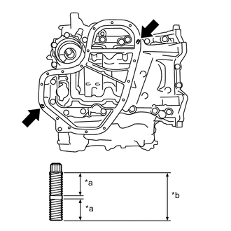
Using an E8 "TORX" socket wrench, install the 2 stud bolts.
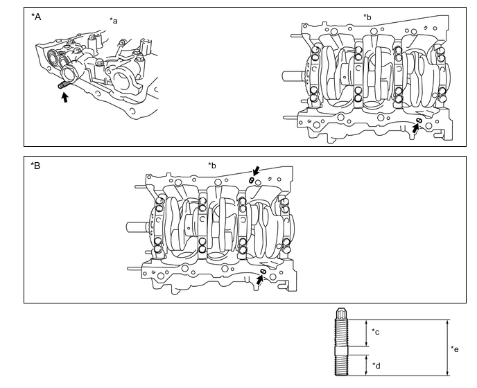
*A Type A *B Type B *a Timing Chain Cover Sub-assembly Side *b Cylinder Block Bottom Side *c 16 mm (0.630 in.) *d 12 mm (0.472 in.) *e 34 mm (1.34 in.) - - - Torque:
- 10 N*m { 102 kgf*cm, 7 ft.*lbf }
-
Install the oil pan sub-assembly.
-
-
INSTALL OIL STRAINER SUB-ASSEMBLY
-
*a Timing Chain Cover Sub-assembly Side *b 16 mm (0.630 in.) *c 9 mm (0.354 in.) *d 27 mm (1.06 in.) Using an E6 "TORX" socket wrench, install the 2 stud bolts as shown in the illustration.
- Torque:
- 4.0 N*m { 41 kgf*cm, 35 in.*lbf }
-
*a Bolt *b Nut Install a new gasket and the oil strainer sub-assembly with the bolt and 2 nuts.
- Torque:
- 10 N*m { 102 kgf*cm, 7 ft.*lbf }
-
-
INSTALL NO. 2 OIL PAN SUB-ASSEMBLY
-
*a 9 mm (0.354 in.) *b 20 mm (0.787 in.) Using an E6 "TORX" socket wrench, install the 2 stud bolts as shown in the illustration.
- Torque:
- 4.0 N*m { 41 kgf*cm, 35 in.*lbf }
-
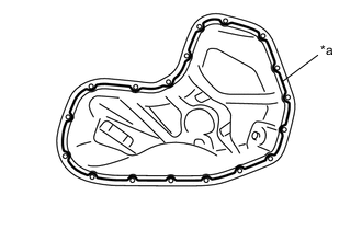
*a Seal Packing Apply seal packing in a continuous line as shown in the illustration.
Seal Packing Toyota Genuine Seal Packing Black, Three Bond 1207B or equivalent Seal Packing Diameter 3.0 to 4.0 mm (0.118 to 0.157 in.) Note
-
Remove any oil from the contact surfaces.
-
Install the No. 2 oil pan sub-assembly within 3 minutes of applying seal packing.
-
Do not start the engine for at least 2 hours after installation.
-
-
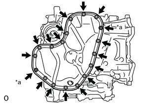
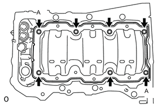
*a Nut Install the No. 2 oil pan sub-assembly with the 16 bolts and 2 nuts.
- Torque:
- 10 N*m { 102 kgf*cm, 7 ft.*lbf }
-
-
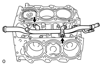
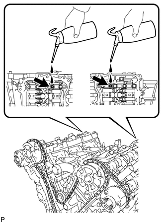
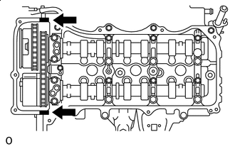
POUR ENGINE OIL
Tech Tips
Before installing the cylinder head cover sub-assemblies, pour engine oil into the oil holes shown in the illustration until the oil holes are filled with engine oil.
-
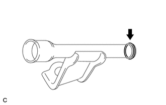
INSTALL SPARK PLUG TUBE GASKET
-
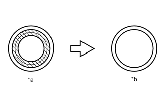
*a Before cutting off *b After cutting off 
Area to be cut off Using a cutter, cut off the sealing part of the removed spark plug tube gasket.
-
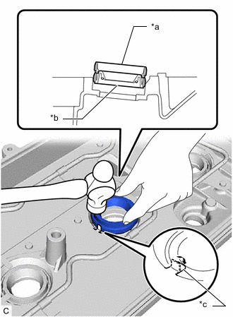
*a Spark Plug Tube Gasket without Sealing Part *b New Spark Plug Tube Gasket *c Claw Using a spark plug tube gasket which has had the sealing part cut off, uniformly press in a new spark plug tube gasket all the way.
Note
-
Keep the lip free from foreign matter.
-
Do not tap in the spark plug tube gasket at an angle.
Tech Tips
If a spark plug tube gasket that will be used to install the spark plug tube gasket is deformed, and cannot be positioned on a new spark plug tube gasket, correct the deformation using pliers.
-
-
Return the claws of the ventilation baffle plate to their original positions.
-
-
INSTALL CYLINDER HEAD COVER SUB-ASSEMBLY
-
Install 3 new gaskets as shown in the illustration.
-
Install a new cylinder head cover gasket to the cylinder head cover sub-assembly.
-
Seal Packing Apply seal packing as shown in the illustration.
Seal Packing Toyota Genuine Seal Packing Black, Three Bond 1207B or equivalent Note
-
Remove any oil from the contact surfaces.
-
Install the cylinder head cover sub-assembly within 3 minutes of applying seal packing.
-
Do not start the engine for at least 2 hours after installation.
-
-

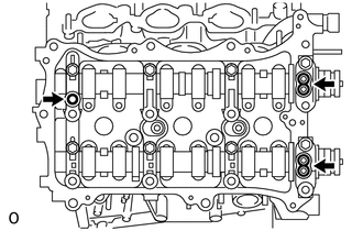
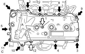
*1 Bolt with Cylinder Head Cover Seal Washer Apply adhesive to these bolts Apply adhesive to the threads of the 10 bolts indicated by the black arrows in the illustration.
Adhesive Toyota Genuine Adhesive 1324, Three Bond 1324 or equivalent Note
Tighten the bolts within 3 minutes of applying adhesive.
-
Install the cylinder head cover sub-assembly with the 12 bolts and a new cylinder head cover seal washer in the order shown in the illustration.
- Torque:
- Bolt (A)
- 21 N*m { 214 kgf*cm, 15 ft.*lbf }
- except Bolt (A)
- 10 N*m { 102 kgf*cm, 7 ft.*lbf }
Tech Tips
After tightening all bolts, check the tightening torque of the bolts (1) and (11). Retighten them if necessary.
-
-
INSTALL CYLINDER HEAD COVER SUB-ASSEMBLY LH
-
Install 3 new gaskets as shown in the illustration.
-
Install a new No. 2 cylinder head cover gasket to the cylinder head cover sub-assembly LH.
-
Seal Packing Apply seal packing as shown in the illustration.
Seal Packing Toyota Genuine Seal Packing Black, Three Bond 1207B or equivalent Note
-
Remove any oil from the contact surfaces.
-
Install the cylinder head cover sub-assembly LH within 3 minutes of applying seal packing.
-
Do not start the engine for at least 2 hours after installation.
-
-
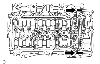
*1 Bolt with Cylinder Head Cover Seal Washer Apply adhesive to these bolts Apply adhesive to the threads of the 10 bolts indicated by the black arrows in the illustration.
Adhesive Toyota Genuine Adhesive 1324, Three Bond 1324 or equivalent Note
Tighten the bolts within 3 minutes of applying adhesive.
-
Install the cylinder head cover sub-assembly LH with the 12 bolts and a new cylinder head cover seal washer in the order shown in the illustration.
- Torque:
- Bolt (A)
- 10 N*m { 102 kgf*cm, 7 ft.*lbf }
- except Bolt (A)
- 21 N*m { 214 kgf*cm, 15 ft.*lbf }
Tech Tips
After tightening all bolts, check the tightening torque of the bolts (1) and (11). Retighten them if necessary.
-
-
INSTALL WATER OUTLET
-
Install 2 new water outlet gaskets and a new O-ring.
Tech Tips
Apply soapy water to the O-ring.
-
*a Nut *b Bolt Install the water outlet with the 2 bolts and 4 nuts.
- Torque:
- 10 N*m { 102 kgf*cm, 7 ft.*lbf }
Note
Make sure that the O-ring does not get caught between the parts.
-
-
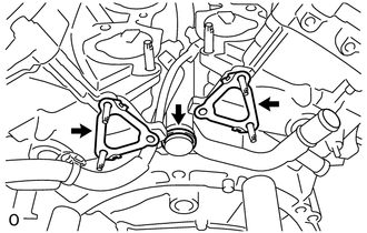
INSTALL FRONT NO. 1 ENGINE MOUNTING BRACKET LH
-
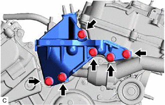
Install the front No. 1 engine mounting bracket LH with the 6 bolts.
- Torque:
- 54 N*m { 551 kgf*cm, 40 ft.*lbf }
Note
-
Install the water inlet and front No. 1 engine mounting bracket LH within 15 minutes of installing the timing chain cover sub-assembly.
-
Do not start the engine for at least 2 hours after installation.
-
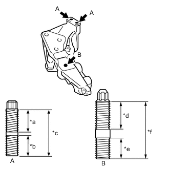
*a 14 mm *b 13 mm *c 29 mm *d 34 mm *e 25 mm *f 76 mm Using an E8 "TORX" socket wrench, install the 2 stud bolts.
- Torque:
- 10 N*m { 102 kgf*cm, 7 ft.*lbf }
-
Using an 8 mm socket wrench, install the stud bolt.
- Torque:
- 10 N*m { 102 kgf*cm, 7 ft.*lbf }
-
-
INSTALL ENGINE OIL LEVEL DIPSTICK GUIDE
-
Apply a light coat of engine oil to a new O-ring and install it to the engine oil level dipstick guide.
-
Install the engine oil level dipstick guide with the bolt.
- Torque:
- 21 N*m { 214 kgf*cm, 15 ft.*lbf }
-
-
INSTALL CRANKSHAFT PULLEY
-
INSTALL OIL FILTER CAP ASSEMBLY
-
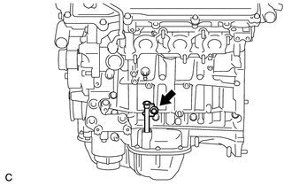
INSTALL CYLINDER BLOCK WATER DRAIN COCK SUB-ASSEMBLY
-
for Bank 1:
-
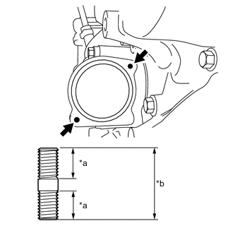
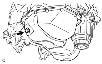
*a Adhesive Apply adhesive to the cylinder block water drain cock sub-assembly.
Adhesive Toyota Genuine Adhesive 1324, Three Bond 1324 or equivalent -
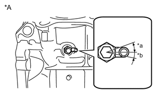
*A for Bank 1 *a 20° *b 12° Install the cylinder block water drain cock sub-assembly as shown in the illustration.
- Torque:
- 25 N*m { 255 kgf*cm, 18 ft.*lbf }
Note
Do not rotate the cylinder block water drain cock sub-assembly more than 1 revolution (360°) after tightening it to the specified torque.
-
Install the cylinder block water drain cock plug to the cylinder block water drain cock sub-assembly.
- Torque:
- 12.7 N*m { 130 kgf*cm, 9 ft.*lbf }
-
-
for Bank 2:
Tech Tips
Perform this procedure only when a cylinder block water drain cock sub-assembly is installed.
-
*a Adhesive Apply adhesive to the cylinder block water drain cock sub-assembly.
Adhesive Toyota Genuine Adhesive 1324, Three Bond 1324 or equivalent -
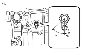
*A for Bank 2 *a 45° *b 15° Install the cylinder block water drain cock sub-assembly as shown in the illustration.
- Torque:
- 25 N*m { 255 kgf*cm, 18 ft.*lbf }
Note
Do not rotate the cylinder block water drain cock sub-assembly more than 1 revolution (360°) after tightening it to the specified torque.
-
Install the cylinder block water drain cock plug to the cylinder block water drain cock sub-assembly.
- Torque:
- 12.7 N*m { 130 kgf*cm, 9 ft.*lbf }
-
-
-
INSTALL TAPER SCREW PLUG
Tech Tips
Perform this procedure only when a taper screw plug is installed.
-
Apply adhesive to the taper screw plug.
Adhesive Toyota Genuine Adhesive 1324, Three Bond 1324 or equivalent -
Install the taper screw plug to the cylinder block sub-assembly.
- Torque:
- 12.7 N*m { 130 kgf*cm, 9 ft.*lbf }
-
-
INSTALL NO. 1 OIL PIPE
-
Make sure that there is no foreign matter on the mesh of the oil control valve filter LH.
Note
Do not touch the mesh when installing the oil control valve filter LH.
-
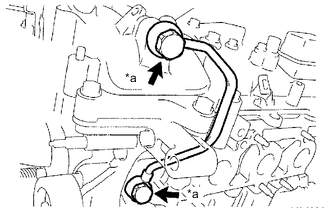
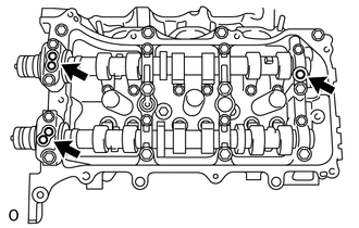
*a Oil Pipe Union Install the oil control valve filter LH to the oil pipe union. Install 2 new gaskets and temporarily install the No. 1 oil pipe (on the cylinder head cover sub-assembly LH side) with the oil pipe union.
-
Install a new gasket and temporarily install the No. 1 oil pipe (on the cylinder head LH side) with the oil pipe union.
-
Tighten the oil pipe union (on the cylinder head cover sub-assembly LH side).
- Torque:
- 65 N*m { 663 kgf*cm, 48 ft.*lbf }
-
Tighten the oil pipe union (on the cylinder head LH side).
- Torque:
- 65 N*m { 663 kgf*cm, 48 ft.*lbf }
Note
If the link that connects the gaskets is broken, remove the link by using side cutters or a similar tool.
-
-
INSTALL OIL PIPE
-
Make sure that there is no foreign matter on the mesh of the oil control valve filter RH.
Note
Do not touch the mesh when installing the oil control valve filter RH.
-
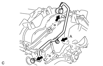
*a Oil Pipe Union Install the oil control valve filter RH to the oil pipe union. Install 2 new gaskets and temporarily install the oil pipe (on the cylinder head cover sub-assembly side) with the oil pipe union.
-
Install a new gasket and temporarily install the oil pipe (on the cylinder head sub-assembly side) with the oil pipe union.
-
Install the bolt (A) to the cylinder head sub-assembly.
- Torque:
- 10 N*m { 102 kgf*cm, 7 ft.*lbf }
-
Tighten the oil pipe union (on the cylinder head cover sub-assembly side).
- Torque:
- 65 N*m { 663 kgf*cm, 48 ft.*lbf }
-
Tighten the oil pipe union (on the cylinder head sub-assembly side).
- Torque:
- 65 N*m { 663 kgf*cm, 48 ft.*lbf }
Note
If the link that connects the gaskets is broken, remove the link by using side cutters or a similar tool.
-
-
INSTALL CRANKSHAFT POSITION SENSOR
-
INSTALL CAMSHAFT TIMING OIL CONTROL VALVE ASSEMBLY LH (for Exhaust Side of Bank 2)
-
INSTALL CAMSHAFT TIMING OIL CONTROL VALVE ASSEMBLY LH (for Intake Side of Bank 2)
-
INSTALL CAMSHAFT TIMING OIL CONTROL VALVE ASSEMBLY RH (for Exhaust Side of Bank 1)
-
INSTALL CAMSHAFT TIMING OIL CONTROL VALVE ASSEMBLY RH (for Intake Side of Bank 1)
-
INSTALL VVT SENSOR (for Exhaust Side of Bank 2)
-
INSTALL VVT SENSOR (for Intake Side of Bank 2)
-
INSTALL VVT SENSOR (for Exhaust Side of Bank 1)
-
INSTALL VVT SENSOR (for Intake Side of Bank 1)
-
INSTALL PCV VALVE (VENTILATION VALVE SUB-ASSEMBLY)
-
INSTALL OIL PAN DRAIN PLUG
-
Install a new oil pan drain plug gasket and the oil pan drain plug.
- Torque:
- 40 N*m { 408 kgf*cm, 30 ft.*lbf }
-
-
INSTALL SPARK PLUG
-
INSTALL OIL FILLER CAP SUB-ASSEMBLY
-
Install a new oil filler cap gasket.
-
Install the oil filler cap sub-assembly.
-