CAMSHAFT REMOVAL
CAUTION / NOTICE / HINT
The necessary procedures (adjustment, calibration, initialization, or registration) that must be performed after parts are removed, installed, or replaced during the camshaft removal/installation are shown below.
| Replacement Part or Procedure | Necessary Procedures | Effects/Inoperative when not Performed | Link |
|---|---|---|---|
| Battery terminal is disconnected/reconnected | Memorize steering angle neutral point | Panoramic view monitor system | |
| Initialize back door lock | Power door lock control system | ||
| Initialize servo motor | Air conditioning system | ||
| Reset slide door close position | Power slide door system | ||
| Reset back door close position | Power back door system | ||
| Replacement of ECM | Perform Vehicle Identification Number (VIN) or frame number registration |
|
|
| ECU Communication ID Registration (Immobiliser system) | Engine start function | See Service Bulletin for the registration method. | |
| Perform code registration (Immobiliser system) |
|
See Service Bulletin for the registration method. | |
|
Inspection After Repair |
|
|
| Replacement of automatic transaxle assembly | Perform the following procedures in the order shown:
|
|
Click here for Initialization Click here for Registration |
| Front wheel alignment adjustment |
|
|
|
| Work that changes the vehicle height such as replacement or removal/installation of the rear height control sensor sub-assembly LH or replacement of suspension components | Initialize headlight light control ECU sub-assembly LH | Headlight leveling function | |
| Removal/installtaion of the radiator grille | Television camera view adjustment | Panoramic view monitor system |
PROCEDURE
-
INSTALL ENGINE ASSEMBLY TO ENGINE STAND
-
REMOVE ENGINE HANGERS
-
REMOVE INTAKE MANIFOLD
-
REMOVE IGNITION COIL ASSEMBLY
-
REMOVE EXHAUST MANIFOLD SUB-ASSEMBLY RH (TWC: Front Catalyst)
-
REMOVE EXHAUST MANIFOLD TO HEAD GASKET
-
REMOVE NO. 2 ENGINE OIL LEVEL DIPSTICK GUIDE
-
INSTALL ENGINE OIL LEVEL DIPSTICK GUIDE
-
REMOVE NO. 2 MANIFOLD STAY
-
REMOVE NO. 2 EXHAUST MANIFOLD HEAT INSULATOR
-
REMOVE EXHAUST MANIFOLD SUB-ASSEMBLY LH (TWC: Front Catalyst)
-
REMOVE EXHAUST MANIFOLD TO HEAD GASKET LH
-
REMOVE V-RIBBED BELT TENSIONER ASSEMBLY
-
REMOVE NO. 2 TIMING GEAR COVER
-
REMOVE WATER PUMP PULLEY
-
REMOVE NO. 2 IDLER PULLEY SUB-ASSEMBLY
-
REMOVE NO. 1 VACUUM SWITCHING VALVE ASSEMBLY
-
REMOVE CRANKSHAFT POSITION SENSOR
-
REMOVE NO. 1 OIL PIPE
-
REMOVE OIL PIPE
-
REMOVE CRANKSHAFT PULLEY
-
REMOVE FRONT NO.1 ENGINE MOUNTING BRACKET LH
-
REMOVE WATER INLET HOUSING
-
REMOVE CYLINDER HEAD COVER SUB-ASSEMBLY
-
REMOVE CYLINDER HEAD COVER SUB-ASSEMBLY LH
-
REMOVE SPARK PLUG TUBE GASKET
-
REMOVE NO. 2 OIL PAN SUB-ASSEMBLY
-
REMOVE OIL STRAINER SUB-ASSEMBLY
-
REMOVE OIL PAN SUB-ASSEMBLY
-
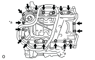
*a Nut Remove the 16 bolts and 2 nuts.
Note
Make sure to clean the bolts and stud bolts and check the threads for cracks or other damage.
-
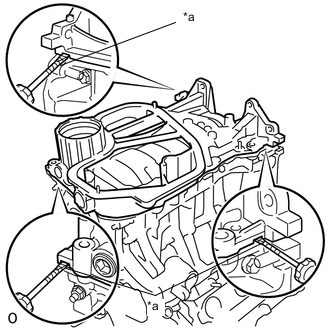
*a Protective Tape Remove the oil pan sub-assembly by prying between the oil pan sub-assembly and cylinder block sub-assembly with a screwdriver wrapped with protective tape.
Note
Be careful not to damage the contact surfaces of the cylinder block sub-assembly and oil pan sub-assembly.
-
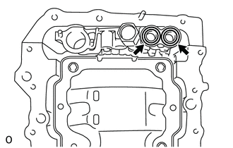
Remove the 2 O-rings.
-
-
REMOVE TIMING CHAIN COVER SUB-ASSEMBLY
-
REMOVE TIMING CHAIN CASE OIL SEAL
-
SET NO. 1 CYLINDER TO TDC/COMPRESSION
-
Temporarily tighten the crankshaft pulley bolt.
-
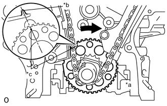
*a Sensor Plate *b Center Line *c Timing Mark Turn the crankshaft clockwise to align the timing mark of the crank angle sensor plate with the center line of the block bore (for Bank 1) (TDC/compression).
-
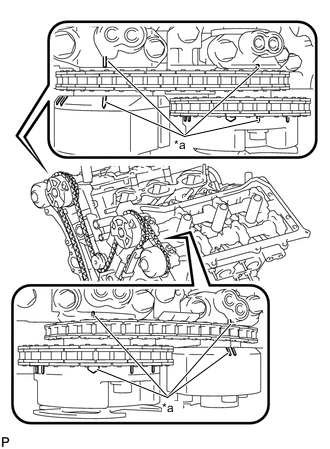
*a Timing Mark Check that the timing marks of the camshaft timing gear assembly and camshaft timing exhaust gear assembly are aligned with the timing marks of the camshaft bearing caps as shown in the illustration.
Tech Tips
If not aligned, turn the crankshaft 1 revolution (360°) clockwise and align the timing marks as shown in the illustration.
-
-
REMOVE NO. 1 CHAIN TENSIONER ASSEMBLY
-
REMOVE CHAIN TENSIONER SLIPPER
-
REMOVE CHAIN SUB-ASSEMBLY
-
REMOVE IDLE SPROCKET ASSEMBLY
-
REMOVE CAMSHAFT TIMING GEAR ASSEMBLY, CAMSHAFT TIMING EXHAUST GEAR ASSEMBLY AND NO. 2 CHAIN SUB-ASSEMBLY (for Bank 1)
-
REMOVE NO. 2 CHAIN TENSIONER ASSEMBLY
-
REMOVE CAMSHAFT BEARING CAP (for Bank 1)
-
REMOVE CAMSHAFT
-
Remove the camshaft.
-
-
REMOVE NO. 2 CAMSHAFT
-
Remove the No. 2 camshaft.
-
-
REMOVE CAMSHAFT HOUSING SUB-ASSEMBLY RH
-
REMOVE CAMSHAFT TIMING GEAR ASSEMBLY, CAMSHAFT TIMING EXHAUST GEAR ASSEMBLY AND NO. 2 CHAIN SUB-ASSEMBLY (for Bank 2)
-
REMOVE NO. 3 CHAIN TENSIONER ASSEMBLY
-
REMOVE CAMSHAFT BEARING CAP (for Bank 2)
-
REMOVE NO. 3 CAMSHAFT SUB-ASSEMBLY
-
Remove the No. 3 camshaft sub-assembly.
-
-
REMOVE NO. 4 CAMSHAFT SUB-ASSEMBLY
-
Remove the No. 4 camshaft sub-assembly.
-
-
REMOVE CAMSHAFT HOUSING SUB-ASSEMBLY LH
-
INSPECT CAMSHAFT TIMING GEAR ASSEMBLY
-
INSPECT CAMSHAFT TIMING EXHAUST GEAR ASSEMBLY