CAMSHAFT INSTALLATION
PROCEDURE
-
INSTALL NO. 3 CAMSHAFT SUB-ASSEMBLY
-
Apply a light coat of engine oil to the No. 3 camshaft sub-assembly journals and camshaft housing sub-assembly LH.
-
Install the No. 3 camshaft sub-assembly to the camshaft housing sub-assembly LH.
Tech Tips
Perform Inspection After Repair after replacing the No. 3 camshaft sub-assembly.
-
-
INSTALL NO. 4 CAMSHAFT SUB-ASSEMBLY
-
Apply a light coat of engine oil to the No. 4 camshaft sub-assembly journals and camshaft housing sub-assembly LH.
-
Install the No. 4 camshaft sub-assembly to the camshaft housing sub-assembly LH.
Tech Tips
Perform Inspection After Repair after replacing the No. 4 camshaft sub-assembly.
-
-
INSTALL CAMSHAFT BEARING CAP (for Bank 2)
-
INSTALL CAMSHAFT HOUSING SUB-ASSEMBLY LH
-
INSTALL CAMSHAFT
-
Apply a light coat of engine oil to the camshaft journals and camshaft housing sub-assembly RH.
-
Install the camshaft to the camshaft housing sub-assembly RH.
-
-
INSTALL NO. 2 CAMSHAFT
-
Apply a light coat of engine oil to the No. 2 camshaft journals and camshaft housing sub-assembly RH.
-
Install the No. 2 camshaft to the camshaft housing sub-assembly RH.
-
-
INSTALL CAMSHAFT BEARING CAP (for Bank 1)
-
INSTALL CAMSHAFT HOUSING SUB-ASSEMBLY RH
-
INSTALL NO. 3 CHAIN TENSIONER ASSEMBLY
-
INSTALL CAMSHAFT TIMING GEAR ASSEMBLY, CAMSHAFT TIMING EXHAUST GEAR ASSEMBLY AND NO. 2 CHAIN SUB-ASSEMBLY (for Bank 2)
-
INSTALL NO. 2 CHAIN TENSIONER ASSEMBLY
-
INSTALL CAMSHAFT TIMING GEAR ASSEMBLY, CAMSHAFT TIMING EXHAUST GEAR ASSEMBLY AND NO. 2 CHAIN SUB-ASSEMBLY (for Bank 1)
-
INSTALL IDLE SPROCKET ASSEMBLY
-
INSTALL CHAIN SUB-ASSEMBLY
-
INSTALL CHAIN TENSIONER SLIPPER
-
INSTALL NO. 1 CHAIN TENSIONER ASSEMBLY
-
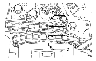
INSPECT VALVE TIMING
-
Check the camshaft timing marks.
Note
-
Check each timing mark from a viewpoint directly in line with the center of the camshaft and the timing mark on each camshaft timing gear assembly and each camshaft timing exhaust gear assembly.
-
If the timing marks are checked from any other viewpoint, the valve timing may appear misaligned.
-
-
Check that each camshaft timing mark is positioned as shown in the illustration.
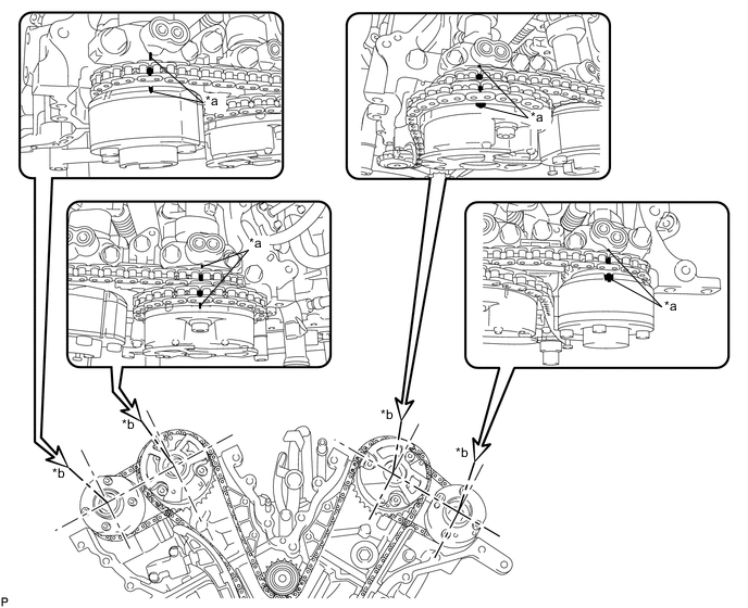
*a Timing Mark *b Viewpoint Tech Tips
For the camshaft or No. 3 camshaft:
Be sure to check the mark (A) at the point where the marks (B), (C), and (D) are positioned in line. If the marks are checked from any other viewpoint, they cannot be checked correctly.
-
If the valve timing is misaligned, reinstall the chain sub-assembly.
-
Remove the crankshaft pulley bolt.
-
-
INSTALL TIMING CHAIN CASE OIL SEAL
-
INSTALL TIMING CHAIN COVER SUB-ASSEMBLY
-
INSTALL OIL PAN SUB-ASSEMBLY
-
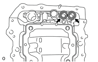
Install 2 new O-rings.
-
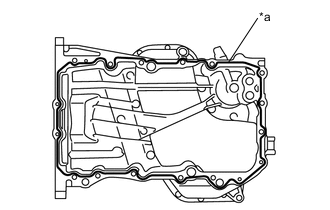
*a Seal Packing Apply seal packing in a continuous line as shown in the illustration.
Seal Packing Toyota Genuine Seal Packing Black, Three Bond 1207B or equivalent Seal Packing Diameter 2.5 to 3.5 mm (0.0985 to 0.1377 in.) Note
-
Remove any oil from the contact surfaces.
-
Install the oil pan sub-assembly within 3 minutes of applying seal packing.
-
Do not start the engine for at least 2 hours after installation.
-
-
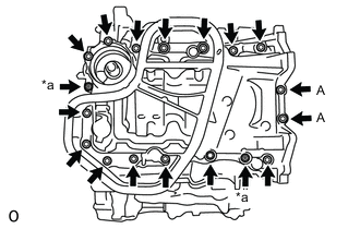
*a Nut Install the oil pan sub-assembly with the 16 bolts and 2 nuts.
- Torque:
- Bolt (A)
- 10 N*m { 102 kgf*cm, 7 ft.*lbf }
- except Bolt (A)
- 21 N*m { 214 kgf*cm, 15 ft.*lbf }
-
-
INSTALL OIL STRAINER SUB-ASSEMBLY
-
INSTALL NO. 2 OIL PAN SUB-ASSEMBLY
-
POUR ENGINE OIL
-
INSTALL SPARK PLUG TUBE GASKET
-
INSTALL CYLINDER HEAD COVER SUB-ASSEMBLY LH
-
INSTALL CYLINDER HEAD COVER SUB-ASSEMBLY
-
INSTALL WATER INLET HOUSING
-
INSTALL FRONT NO. 1 ENGINE MOUNTING BRACKET LH
-
INSTALL CRANKSHAFT PULLEY
-
INSTALL OIL PIPE
-
INSTALL NO. 1 OIL PIPE
-
INSTALL CRANKSHAFT POSITION SENSOR
-
INSTALL NO. 1 VACUUM SWITCHING VALVE ASSEMBLY
-
INSTALL NO. 2 IDLER PULLEY SUB-ASSEMBLY
-
INSTALL WATER PUMP PULLEY
-
INSTALL NO. 2 TIMING GEAR COVER
-
INSTALL V-RIBBED BELT TENSIONER ASSEMBLY
-
INSTALL EXHAUST MANIFOLD TO HEAD GASKET LH
-
INSTALL EXHAUST MANIFOLD SUB-ASSEMBLY LH (TWC: Front Catalyst)
-
INSTALL NO. 2 EXHAUST MANIFOLD HEAT INSULATOR
-
INSTALL NO. 2 MANIFOLD STAY
-
INSTALL ENGINE OIL LEVEL DIPSTICK GUIDE
-
INSTALL NO. 2 ENGINE OIL LEVEL DIPSTICK GUIDE
-
INSTALL EXHAUST MANIFOLD TO HEAD GASKET
-
INSTALL EXHAUST MANIFOLD SUB-ASSEMBLY RH (TWC: Front Catalyst)
-
INSTALL IGNITION COIL ASSEMBLY
-
INSTALL INTAKE MANIFOLD
-
INSTALL ENGINE HANGERS
-
REMOVE ENGINE ASSEMBLY FROM ENGINE STAND