CYLINDER BLOCK INSPECTION
PROCEDURE
-
INSPECT CYLINDER BLOCK FOR WARPAGE
-
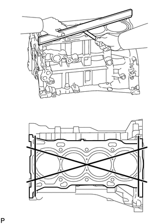
Using a precision straightedge and feeler gauge, measure the warpage of the surface which contacts the cylinder head gasket.
Maximum Warpage 0.05 mm (0.00197 in.) If the warpage is more than the maximum, replace the cylinder block sub-assembly.
-
-
INSPECT CYLINDER BORE
-
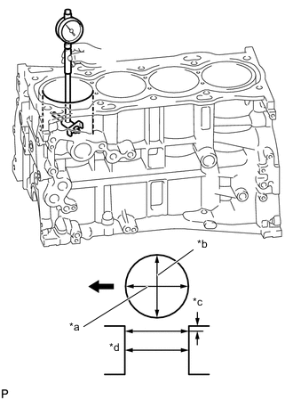
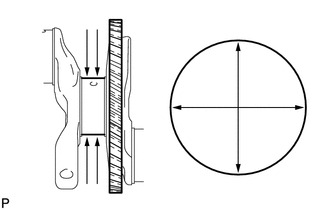
*a Axial Direction *b Thrust Direction *c 10 mm (0.394 in.) 
Front of Engine Using a cylinder gauge, measure the cylinder bore diameter at the positions (A) and (B) in the thrust and axial directions.
Reference Diameter (New Parts) 90.000 to 90.013 mm (3.5433 to 3.5438 in.) Maximum Diameter 90.13 mm (3.5484 in.) If the average diameter of the 4 positions is more than the maximum, replace the cylinder block sub-assembly.
-
-
INSPECT PISTON
-
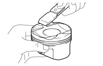
Using a gasket scraper, remove any carbon from the piston top.
-
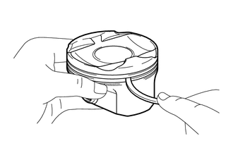
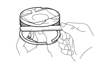
Using a groove cleaning tool or a broken ring, clean the piston ring grooves.
-
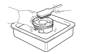
Using a brush and solvent, thoroughly clean the piston.
Note
Do not use a wire brush.
-
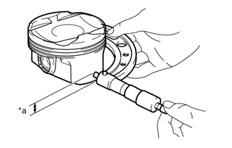
*a Distance Using a micrometer, measure the piston diameter at a right angle to the piston center line where the distance from the bottom of the piston is as specified.
Distance 10.5 mm (0.413 in.) Standard Piston Diameter (New Parts) 89.980 to 89.995 mm (3.5425 to 3.5431 in.) If the diameter is less than the minimum, replace the piston.
-
-
INSPECT PISTON OIL CLEARANCE
-
Subtract the piston diameter measurement from the cylinder bore diameter measurement.
Reference Oil Clearance (New Parts) 0.004 to 0.042 mm (0.000158 to 0.00165 in.) Maximum Oil Clearance 0.10 mm (0.00394 in.) If the oil clearance is more than the maximum, replace all the pistons. If necessary, replace the cylinder block sub-assembly.
-
-
INSPECT RING GROOVE CLEARANCE
-
Using a feeler gauge, measure the clearance between the piston ring set and the wall of the ring groove.
Standard Ring Groove Clearance Item Specified Condition No. 1 compression ring 0.020 to 0.070 mm (0.000787 to 0.00276 in.) No. 2 compression ring 0.020 to 0.060 mm (0.000787 to 0.00236 in.) Oil ring 0.020 to 0.070 mm (0.000787 to 0.00276 in.) If the groove clearance is not as specified, replace the piston.
-
-
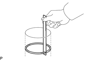
INSPECT PISTON RING END GAP
-
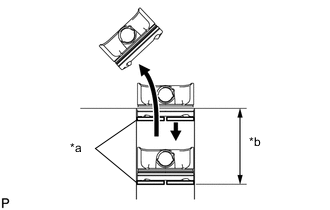
*a Piston Ring *b 120 mm (4.72 in.) Insert the piston ring into the cylinder bore.
-
Using a piston, push in the piston ring a little beyond the bottom of the ring travel, 120 mm (4.72 in.) from the top of the cylinder block sub-assembly.
-
Using a feeler gauge, measure the end gap.
Standard End Gap Item Specified Condition No. 1 compression ring 0.22 to 0.27 mm (0.00866 to 0.0106 in.) No. 2 compression ring 0.37 to 0.42 mm (0.0146 to 0.0165 in.) Oil ring 0.10 to 0.20 mm (0.00394 to 0.00787 in.) Maximum End Gap Item Specified Condition No. 1 compression ring 0.87 mm (0.0343 in.) No. 2 compression ring 1.02 mm (0.0402 in.) Oil ring 0.80 mm (0.0315 in.) If the end gap is more than the maximum, replace the piston ring set. If the end gap is more than the maximum even with a new piston ring set, replace the cylinder block sub-assembly.
-
-
INSPECT PISTON PIN OIL CLEARANCE
-
Confirm each mark on the piston, piston pin and connecting rod.
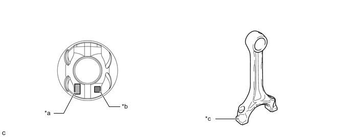
*a Front Mark *b Piston Pin Hole Inside Diameter Mark *c Connecting Rod Small End Bush Inside Diameter Mark - - -
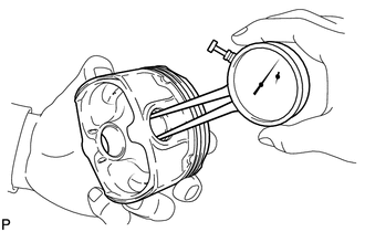
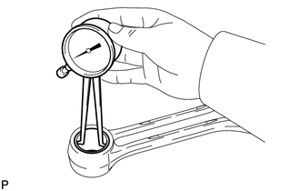
Using a caliper gauge, measure the inside diameter of the piston pin hole.
Standard Piston Pin Hole Inside Diameter Mark Specified Condition A 22.001 to 22.004 mm (0.86618 to 0.86630 in.) B 22.005 to 22.007 mm (0.86634 to 0.86642 in.) C 22.008 to 22.010 mm (0.86645 to 0.86653 in.) -
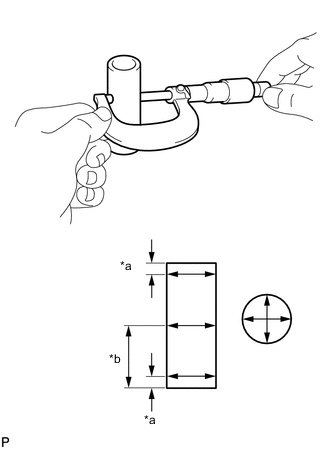
*a 5.0 mm (0.197 in.) *b 28 mm (1.10 in.) Using a micrometer, measure the piston pin diameter.
Standard Piston Pin Diameter Mark Specified Condition A 21.997 to 22.000 mm (0.86602 to 0.86614 in.) B 22.001 to 22.003 mm (0.86618 to 0.86626 in.) C 22.004 to 22.006 mm (0.86630 to 0.86638 in.) If the diameter is not as specified, replace the piston and piston pin as a set.
-
Using a caliper gauge, measure the inside diameter of the connecting rod small end bush.
Standard Connecting Rod Small End Bush Inside Diameter Mark Specified Condition A 22.005 to 22.008 mm (0.86634 to 0.86645 in.) B 22.009 to 22.011 mm (0.86649 to 0.86657 in.) C 22.012 to 22.014 mm (0.86661 to 0.86669 in.) If the inside diameter is not as specified, replace the connecting rod.
-
Subtract the piston pin diameter measurement from the piston pin hole inside diameter measurement.
Standard Oil Clearance 0.001 to 0.007 mm (0.0000394 to 0.000276 in.) Maximum Oil Clearance 0.013 mm (0.000512 in.) If the oil clearance is more than the maximum, replace the piston and piston pin as a set.
-
Subtract the piston pin diameter measurement from the connecting rod small end bush inside diameter measurement.
Standard Oil Clearance 0.005 to 0.011 mm (0.000197 to 0.000433 in.) Maximum Oil Clearance 0.017 mm (0.000669 in.) If the oil clearance is more than the maximum, replace the connecting rod. If necessary, replace the connecting rod and piston pin as a set.
-
-
INSPECT CONNECTING ROD
-
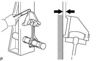
Using a connecting rod aligner and feeler gauge, check the connecting rod alignment.
-
Check for misalignment.
Maximum Misalignment 0.05 mm (0.00197 in.) per 100 mm (3.94 in.) If the misalignment is more than the maximum, replace the connecting rod.
-
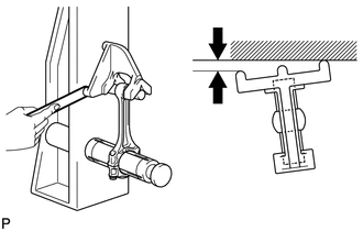
Check for twist.
Maximum Twist 0.15 mm (0.00591 in.) per 100 mm (3.94 in.) If the twist is more than the maximum, replace the connecting rod.
-
-
-
INSPECT CRANKSHAFT
-
Inspect for runout.
-
Clean the crank journal.
-
Place the crankshaft on V-blocks.
-
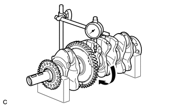
Using a dial indicator and V-blocks, measure the runout as shown in the illustration.
Maximum Runout 0.03 mm (0.00118 in.) If the runout is more than the maximum, replace the crankshaft.
-
-
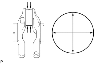
Inspect the main journals.
-
Using a micrometer, measure the diameter of each main journal.
Standard Main Journal Diameter 54.988 to 55.000 mm (2.16 to 2.17 in.) If the diameter is not as specified, check the crankshaft oil clearance. If necessary, replace the crankshaft.
-
Check each main journal for taper and out-of-round as shown in the illustration.
Maximum Taper and Out-of-round 0.003 mm (0.000118 in.) If the taper or out-of-round is more than the maximum, replace the crankshaft.
-
-
Inspect the crank pin.
-
Using a micrometer, measure the diameter of each crank pin.
Standard Crank Pin Diameter 51.492 to 51.500 mm (2.02724 to 2.02756 in.) If the diameter is not as specified, check the connecting rod oil clearance. If necessary, replace the crankshaft.
-
Inspect each crank pin for taper and out-of-round as shown in the illustration.
Maximum Taper and Out-of-round 0.003 mm (0.000118 in.) If the taper or out-of-round is more than the maximum, replace the crankshaft.
-
-
-
INSPECT CRANKSHAFT OIL CLEARANCE
-
Install the crankshaft bearings.
-
Install the crankshaft thrust washers.
-
Place the crankshaft on the cylinder block sub-assembly.
-
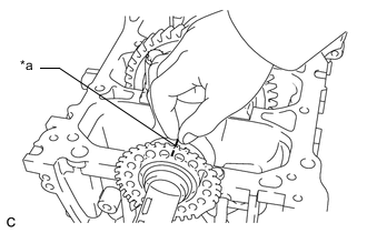
*a Plastigage Lay a strip of Plastigage across each journal.
-
Install the crankshaft bearing caps.
Note
Do not turn the crankshaft.
-
Remove the crankshaft bearing caps.
-
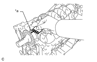
*a Plastigage Measure the Plastigage at its widest point.
Standard Oil Clearance 0.017 to 0.040 mm (0.000669 to 0.00157 in.) Maximum Oil Clearance 0.05 mm (0.00197 in.) Note
Remove the Plastigage completely after the measurement.
If the oil clearance is more than the maximum, replace the crankshaft bearing. If necessary, replace the crankshaft.
-
Perform the inspection for each journal.
-
-
INSPECT CRANKSHAFT BEARING CAP BOLT
-
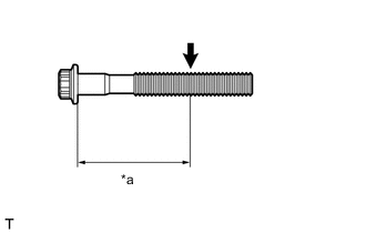
*a Measurement Point Using a vernier caliper, measure the diameter of the threads at the measurement point shown in the illustration.
Standard Diameter 9.77 to 9.96 mm (0.385 to 0.392 in.) Minimum Diameter 9.1 mm (0.358 in.) Measurement Point (Distance from the Seat) 58.5 mm (2.30 in.) Tech Tips
-
If the diameter is less than the minimum, replace the crankshaft bearing cap bolt. Failure to do so may lead to engine damage.
-
If there is any thread deformation, replace the crankshaft bearing cap bolt with a new one.
-
-
-
INSPECT CONNECTING ROD BOLT
-
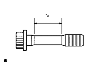
*a Measurement Area Using a vernier caliper, measure the diameter of the connecting rod bolt at several points within the area shown in the illustration.
Standard Diameter 8.5 to 8.6 mm (0.335 to 0.339 in.) Minimum Diameter 8.3 mm (0.327 in.) Tech Tips
-
Diameter measurements should be done at several points.
-
If the diameter is less than the minimum, replace the connecting rod bolt. Failure to do so may lead to engine damage.
-
If there is any thread deformation, replace the connecting rod bolt with a new one.
-
-
-
INSPECT NO. 1 OIL NOZZLE SUB-ASSEMBLY
-
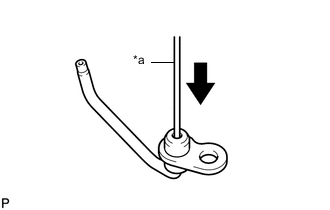
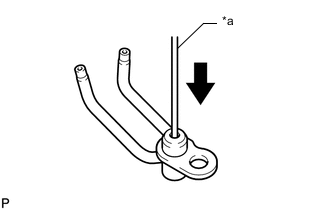
*a Pin Push the check valve with a pin to check that it is not stuck.
If the check valve is stuck, replace the No. 1 oil nozzle sub-assembly.
-
Push the check valve with a pin to check if it moves smoothly.
If the check valve does not move smoothly, clean or replace the No. 1 oil nozzle sub-assembly.
-
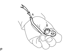
Apply air to (A). Check that air does not leak through (B).
If air leaks, clean or replace the No. 1 oil nozzle sub-assembly.
-
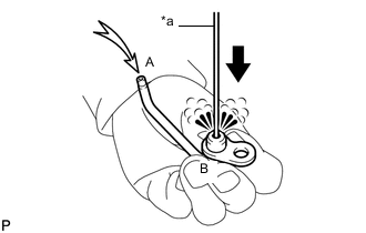
*a Pin While pushing the check valve with a pin, apply air to (A). Check that air passes through (B).
If air does not pass through (B), clean or replace the No. 1 oil nozzle sub-assembly.
-
-
INSPECT NO. 2 OIL NOZZLE SUB-ASSEMBLY
-
*a Pin Push the check valve with a pin to check that it is not stuck.
If the check valve is stuck, replace the No. 2 oil nozzle sub-assembly.
-
Push the check valve with a pin to check if it moves smoothly.
If the check valve does not move smoothly, clean or replace the No. 2 oil nozzle sub-assembly.
-
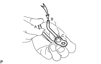
While covering (A), apply air into (B). Check that air does not leak through (C). Perform the check again while covering (B) and applying air into (A).
If air leaks, clean or replace the No. 2 oil nozzle sub-assembly.
-
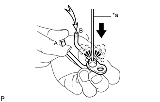
*a Pin While pushing the check valve with a pin, cover (A) and apply air to (B). Check that air passes through (C). While continuing to push the check valve with a pin, cover (B) and apply air to (A).
If air does not pass through (C), clean or replace the No. 2 oil nozzle sub-assembly.
-