CYLINDER BLOCK DISASSEMBLY
CAUTION / NOTICE / HINT
The necessary procedures (adjustment, calibration, initialization, or registration) that must be performed after parts are removed, installed, or replaced during the engine unit removal/installation are shown below.
| Replacement Part or Procedure | Necessary Procedures | Effects/Inoperative when not Performed | Link |
|---|---|---|---|
| Battery terminal is disconnected/reconnected | Drive the vehicle until stop and start control is permitted (approximately 5 to 60 minutes) | Stop and start system | |
| Memorize steering angle neutral point | Panoramic view monitor system | ||
| Initialize back door lock | Power door lock control system | ||
| Initialize servo motor | Air conditioning system | ||
| Reset slide door close position | Power slide door system | ||
| Reset back door close position | Power back door system | ||
| Replacement of ECM | Perform Vehicle Identification Number (VIN) or frame number registration | DTC is stored | |
| ECU Communication ID Registration (Immobiliser system) | Engine start function | See Service Bulletin for the registration method. | |
| Perform code registration (Immobiliser system) |
|
See Service Bulletin for the registration method. | |
| Perform the following procedures in the order shown:
|
|
||
| Replacement of continuously variable transaxle assembly | Perform the following procedures in the order shown:
|
|
|
| Replacement of CVT fluid | ATF thermal degradation estimate reset | The value of the Data List item "ATF Thermal Degradation Estimate" is not estimated correctly | |
|
Inspection After Repair |
|
|
| Replacement of starter assembly Note When the starter assembly is replaced, "ST NO. 1 relay" and "ST NO. 2 relay" must be also replaced. |
Clear Number of Starter Operations | Stop and start system | |
|
Bleed the oil pump assembly with motor (continuously variable transaxle assembly) | ||
| Replacement of battery | Switch battery type | ||
| Front wheel alignment adjustment |
|
|
|
| Work that changes the vehicle height such as replacement or removal/installation of the rear height control sensor sub-assembly LH or replacement of suspension components | Initialize headlight light control ECU sub-assembly LH | Headlight leveling function | |
| Removal/installtaion of the radiator grille | Television camera view adjustment | Panoramic view monitor system |
PROCEDURE
-
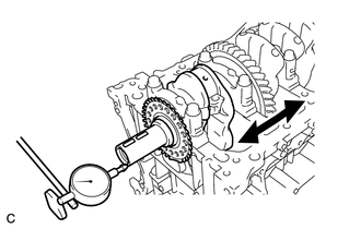
INSPECT CONNECTING ROD THRUST CLEARANCE
-
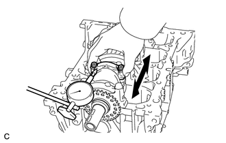
Using a dial indicator, measure the thrust clearance while moving the connecting rod sub-assembly back and forth.
Standard Thrust Clearance 0.160 to 0.512 mm (0.00630 to 0.0202 in.) Maximum Thrust Clearance 0.512 mm (0.0202 in.) If the thrust clearance is more than the maximum, replace the connecting rod. If necessary, replace the crankshaft.
-
-
INSPECT CONNECTING ROD OIL CLEARANCE
-
*a Alignment Mark Check the alignment marks on the connecting rod and connecting rod cap so that they can be reinstalled to their original locations.
-
Remove the 2 connecting rod bolts and connecting rod cap.
Tech Tips
Keep the connecting rod bearing and connecting rod cap together.
-
Clean the crank pin and connecting rod bearing.
-
Check the crank pin and connecting rod bearing for pitting and scratches.
If the crank pin or connecting rod bearing is damaged, replace the connecting rod bearings. If necessary, replace the crankshaft.
-
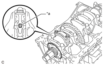
*a Plastigage Lay a strip of Plastigage on the crank pin.
-
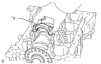
*a Front Mark Check that the front mark of the connecting rod cap is facing the correct direction, and install the connecting rod cap.
-
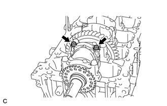
Apply a light coat of engine oil to the threads and under the heads of the 2 connecting rod bolts.
-
Install and alternately tighten the 2 connecting rod bolts in several steps.
- Torque:
- 40 N*m { 408 kgf*cm, 30 ft.*lbf }
-
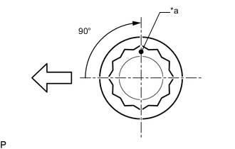
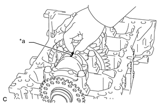
*a Paint Mark 
Front of Engine Mark the front of each connecting rod bolt with paint.
-
Tighten the connecting rod bolts 90° as shown in the illustration.
Note
Do not turn the crankshaft during the measurement.
-
Remove the 2 connecting rod bolts and connecting rod cap.
Tech Tips
Keep the connecting rod bearing and connecting rod cap together.
-
Type A:
-
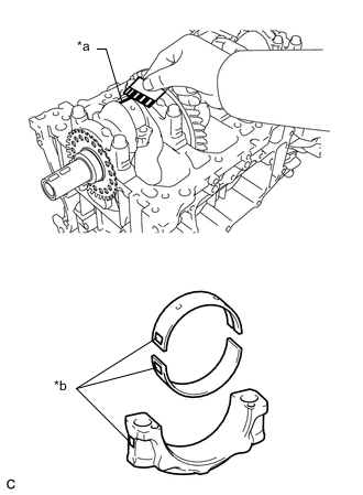
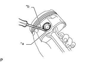
*a Plastigage *b Number Mark Measure the Plastigage at its widest point.
Standard Oil Clearance 0.030 to 0.063 mm (0.00118 to 0.00248 in.) Maximum Oil Clearance 0.07 mm (0.00276 in.) Note
Remove the Plastigage completely after the measurement.
If the oil clearance is more than the maximum, replace the connecting rod bearings. If necessary, replace the crankshaft.
Tech Tips
If replacing a connecting rod bearing, select a new one with the same number as marked on the connecting rod cap. There are 3 sizes of standard connecting rod bearings, marked "1", "2" or "3" accordingly.
Standard Crank Pin Diameter 51.492 to 51.500 mm (2.02724 to 2.02756 in.) Standard Connecting Rod Big End Inside Diameter Mark Specified Condition 1 54.500 to 54.508 mm (2.14567 to 2.14598 in.) 2 54.509 to 54.516 mm (2.14602 to 2.14629 in.) 3 54.517 to 54.524 mm (2.14633 to 2.14661 in.) Standard Connecting Rod Bearing Center Wall Thickness Mark Specified Condition 1 1.486 to 1.490 mm (0.0585 to 0.0587 in.) 2 1.491 to 1.494 mm (0.0587 to 0.0588 in.) 3 1.495 to 1.498 mm (0.0589 to 0.0590 in.)
-
-
Type B:
-
*a Plastigage *b Number Mark Measure the Plastigage at its widest point.
Standard Oil Clearance 0.033 to 0.063 mm (0.00130 to 0.00248 in.) Maximum Oil Clearance 0.07 mm (0.00276 in.) Note
Remove the Plastigage completely after the measurement.
If the oil clearance is more than the maximum, replace the connecting rod bearings. If necessary, replace the crankshaft.
Tech Tips
If replacing a connecting rod bearing, select a new one with the same number as marked on the connecting rod cap. There are 3 sizes of standard connecting rod bearings, marked "1", "2" or "3" accordingly.
Standard Crank Pin Diameter 51.492 to 51.500 mm (2.02724 to 2.02756 in.) Standard Connecting Rod Big End Inside Diameter Mark Specified Condition 1 54.500 to 54.508 mm (2.14567 to 2.14598 in.) 2 54.509 to 54.516 mm (2.14602 to 2.14629 in.) 3 54.517 to 54.524 mm (2.14633 to 2.14661 in.) Standard Connecting Rod Bearing Center Wall Thickness Mark Specified Condition 1 1.486 to 1.490 mm (0.0585 to 0.0587 in.) 2 1.491 to 1.494 mm (0.0587 to 0.0588 in.) 3 1.495 to 1.498 mm (0.0589 to 0.0590 in.)
-
-
Perform the inspection above for each cylinder.
-
-
REMOVE PISTON WITH CONNECTING ROD
-
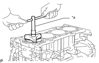
*a Ridge Reamer Using a ridge reamer, remove all the carbon from the top of each cylinder.
-
Remove the 8 connecting rod bolts, 4 connecting rod caps and 4 connecting rod bearings.
-
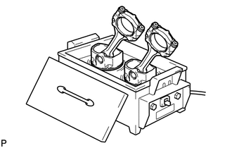
Push the piston with connecting rod and connecting rod bearing out through the top of the cylinder block sub-assembly.
Tech Tips
-
Keep the connecting rod bearings, connecting rod and connecting rod cap together.
-
Arrange the removed parts in such a way that they can be reinstalled to their original locations.
-
-
-
REMOVE CONNECTING ROD BEARING
-
Remove the connecting rod bearings from the connecting rod and connecting rod cap.
Tech Tips
Arrange the removed parts in such a way that they can be reinstalled to their original locations.
-
-
INSPECT CRANKSHAFT THRUST CLEARANCE
-
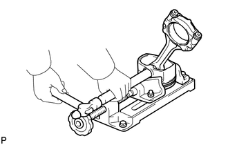
Using a dial indicator, measure the thrust clearance while prying the crankshaft back and forth with a screwdriver.
Standard Thrust Clearance 0.04 to 0.24 mm (0.00157 to 0.00945 in.) Maximum Thrust Clearance 0.30 mm (0.0118 in.) If the thrust clearance is more than the maximum, replace the crankshaft thrust washers as a set. If necessary, replace the crankshaft.
Standard Thrust Washer Thickness 1.93 to 1.98 mm (0.0760 to 0.0780 in.)
-
-
REMOVE CRANKSHAFT
-
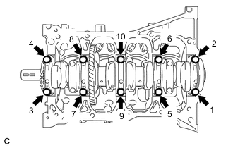
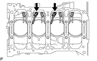
Uniformly loosen and remove the 10 crankshaft bearing cap bolts in several steps in the order shown in the illustration.
-
Remove the 5 crankshaft bearing caps from the cylinder block sub-assembly.
Tech Tips
-
Keep the No. 2 crankshaft bearings and crankshaft bearing caps together.
-
Arrange the removed parts in such a way that they can be reinstalled to their original locations.
-
-
Remove the crankshaft from the cylinder block sub-assembly.
Tech Tips
Keep the crankshaft bearings and crankshaft thrust washers together with the cylinder block sub-assembly.
-
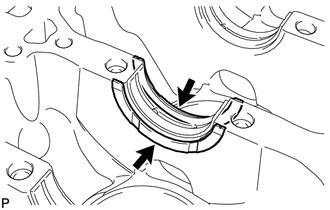
Check each crankshaft journal and crankshaft bearing for pitting and scratches.
If the journal or crankshaft bearing is damaged, replace the crankshaft bearings. If necessary, replace the crankshaft.
-
-
REMOVE CRANKSHAFT THRUST WASHER
-
Remove the crankshaft thrust washers from the cylinder block sub-assembly.
-
-
REMOVE CRANKSHAFT BEARING
-
Remove the crankshaft bearings and No. 2 crankshaft bearings from the cylinder block sub-assembly and crankshaft bearing caps.
Tech Tips
Arrange the removed parts in such a way that they can be reinstalled to their original locations.
-
-
REMOVE CRANKSHAFT PULLEY KEY
-
Using a screwdriver, remove the 2 crankshaft pulley keys from the crankshaft.
-
-
REMOVE PISTON RING SET
-
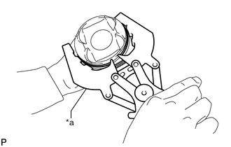
*a Piston Ring Expander Using a piston ring expander, remove the No. 1 compression ring and No. 2 compression ring.
-
Remove the oil ring expander, upper side rail and lower side rail by hand.
Tech Tips
Arrange the removed parts in such a way that they can be reinstalled to their original locations.
-
-
REMOVE PISTON PIN HOLE SNAP RING
-
*a Front Mark Cutout Portion *b Protective Tape Using a screwdriver, pry out the piston pin hole snap ring (front side).
Note
-
Do not remove the piston pin hole snap ring (rear side) unless it has to be replaced.
-
Be careful not to damage the piston when removing the piston pin hole snap ring (rear side).
Tech Tips
Tape the screwdriver tip before use.
-
-
-
REMOVE PISTON
-
Gradually heat each piston to between 80 and 90°C (176 to 194°F).
-
Using a brass bar and a hammer, lightly tap out the piston pin. Then remove the connecting rod.
Tech Tips
-
The piston and piston pin are a matched set.
-
Arrange the removed parts in such a way that they can be reinstalled to their original locations.
-
-
-
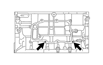
REMOVE NO. 1 OIL NOZZLE SUB-ASSEMBLY
-
Using a 5 mm hexagon wrench, remove the 2 bolts and 2 No. 1 oil nozzle sub-assemblies.
-
-
REMOVE NO. 2 OIL NOZZLE SUB-ASSEMBLY
-
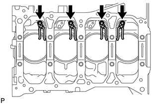
Using a 5 mm hexagon wrench, remove the 4 bolts and 4 No. 2 oil nozzle sub-assemblies.
-
-
REMOVE STUD BOLT
Note
If a stud bolt is deformed or its threads are damaged, replace it.
-
Using an E8 "TORX" socket wrench, remove the 2 stud bolts.
-