ENGINE ASSEMBLY REMOVAL
CAUTION / NOTICE / HINT
The necessary procedures (adjustment, calibration, initialization, or registration) that must be performed after parts are removed, installed, or replaced during the engine assembly removal/installation are shown below.
| Replacement Part or Procedure | Necessary Procedures | Effects/Inoperative when not Performed | Link |
|---|---|---|---|
| Battery terminal is disconnected/reconnected | Drive the vehicle until stop and start control is permitted (approximately 5 to 60 minutes) | Stop and start system | |
| Memorize steering angle neutral point | Panoramic view monitor system | ||
| Initialize back door lock | Power door lock control system | ||
| Initialize servo motor | Air conditioning system | ||
| Reset slide door close position | Power slide door system | ||
| Reset back door close position | Power back door system | ||
| Replacement of ECM | Perform Vehicle Identification Number (VIN) or frame number registration | DTC is stored | |
| ECU Communication ID Registration (Immobiliser system) | Engine start function | See Service Bulletin for the registration method. | |
| Perform code registration (Immobiliser system) |
|
See Service Bulletin for the registration method. | |
| Perform the following procedures in the order shown:
|
|
||
| Replacement of continuously variable transaxle assembly | Perform the following procedures in the order shown:
|
|
|
| Replacement of CVT fluid | ATF thermal degradation estimate reset | The value of the Data List item "ATF Thermal Degradation Estimate" is not estimated correctly | |
|
Inspection After Repair |
|
|
| Replacement of starter assembly Note When the starter assembly is replaced, "ST NO. 1 relay" and "ST NO. 2 relay" must be also replaced. |
Clear Number of Starter Operations | Stop and start system | |
|
Bleed the oil pump assembly with motor (continuously variable transaxle assembly) | ||
| Replacement of battery | Switch battery type | ||
| Front wheel alignment adjustment |
|
|
|
| Work that changes the vehicle height such as replacement or removal/installation of the rear height control sensor sub-assembly LH or replacement of suspension components | Initialize headlight light control ECU sub-assembly LH | Headlight leveling function | |
| Removal/installtaion of the radiator grille | Television camera view adjustment | Panoramic view monitor system |
CAUTION:
-
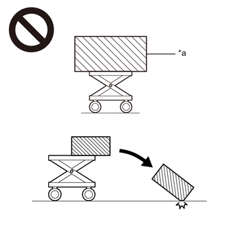
*a An Object Exceeding Weight Limit of Engine Lifter The engine assembly with transaxle is very heavy. Be sure to follow the procedure described in the repair manual, or the engine lifter may suddenly drop or the engine assembly with transaxle may fall off the engine lifter.
-
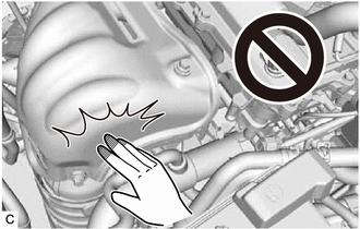
To prevent burns, do not touch the engine, exhaust manifold or other high temperature components while the engine is hot.
PROCEDURE
-
PRECAUTION
Note
After turning the engine switch off, waiting time may be required before disconnecting the cable from the negative (-) battery terminal. Therefore, make sure to read the disconnecting the cable from the negative (-) battery terminal notices before proceeding with work.
-
RECOVER REFRIGERANT FROM REFRIGERATION SYSTEM
-
DISCHARGE FUEL SYSTEM PRESSURE
-
DISCONNECT CABLE FROM NEGATIVE BATTERY TERMINAL
Note
When disconnecting the cable, some systems need to be initialized after the cable is reconnected.
-
ALIGN FRONT WHEELS FACING STRAIGHT AHEAD
-
SECURE STEERING WHEEL
-
REMOVE FRONT WHEELS
-
REMOVE FRONT BUMPER COVER
for ALPHARD: Click here
for VELLFIRE: Click here
-
REMOVE FRONT LOWER BUMPER ABSORBER
-
REMOVE NO. 1 ENGINE UNDER COVER
-
Remove the 2 bolts, 5 clips and No. 1 engine under cover.
-
-
REMOVE NO. 2 ENGINE UNDER COVER
-
Remove the 5 clips and No. 2 engine under cover.
-
-
REMOVE REAR ENGINE UNDER COVER LH
-
Remove the 5 clips and rear engine under cover LH.
-
-
REMOVE REAR ENGINE UNDER COVER RH
-
Remove the 5 clips and rear engine under cover RH.
-
-
DRAIN ENGINE COOLANT
-
DRAIN ENGINE OIL
-
DRAIN CONTINUOUSLY VARIABLE TRANSAXLE FLUID
-
REMOVE OUTER COWL TOP PANEL SUB-ASSEMBLY
-
REMOVE RADIATOR RESERVE TANK ASSEMBLY
-
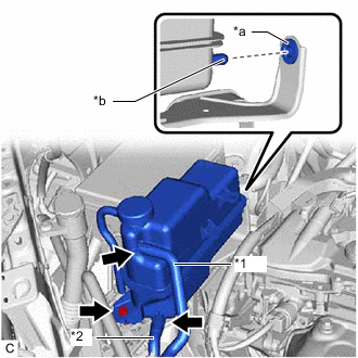
*1 Water By-pass Hose *2 No. 2 Water By-pass Hose *a Grommet *b Protrusion Slide the 2 clips and disconnect the water by-pass hose and No. 2 water by-pass hose from the radiator reserve tank assembly.
-
Remove the bolt and radiator reserve tank assembly from the radiator reserve tank bracket.
-
-
REMOVE RADIATOR RESERVE TANK BRACKET
-
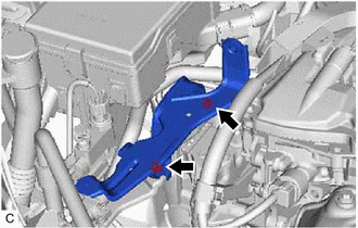
Remove the 2 bolts and radiator reserve tank bracket.
-
-
REMOVE ECM
-
REMOVE BATTERY CARRIER
-
REMOVE BATTERY CARRIER SUPPORT
-
REMOVE V-RIBBED BELT
-
REMOVE GENERATOR ASSEMBLY
-
DISCONNECT NO. 2 RADIATOR HOSE
-
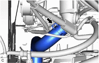
Slide the clip and disconnect the No. 2 radiator hose from the water inlet.
-
-
DISCONNECT NO. 1 RADIATOR HOSE
-
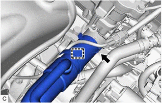
Remove the radiator hose clamp to disconnect the air fuel ratio sensor wire from the No. 1 radiator hose.
-
Slide the clip and disconnect the No. 1 radiator hose from the cylinder head sub-assembly.
-
-
DISCONNECT NO. 1 COOLER REFRIGERANT SUCTION HOSE
-
DISCONNECT NO. 1 COOLER REFRIGERANT DISCHARGE HOSE
-
DISCONNECT HEATER HOSE
-
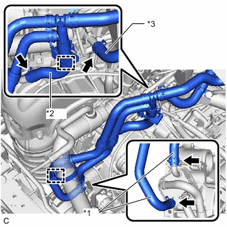
*1 No. 2 Water By-pass Hose *2 Water Hose Sub-assembly *3 Heater Water Inlet Hose Disengage the clamp and disconnect the No. 2 water by-pass hose from the No. 1 radiator hose.
-
Slide the 2 clips and disconnect the No. 2 water by-pass hose from the oil cooler.
-
Disengage the clamp and disconnect the water hose sub-assembly.
-
Slide the clip and disconnect the water hose sub-assembly from the No. 1 water by-pass pipe.
-
Slide the clip and disconnect the heater water inlet hose from the cylinder head sub-assembly.
-
-
DISCONNECT WIRE HARNESS
Tech Tips
After disconnecting the wire harness, secure it with tape or equivalent to keep it out of the way.
-
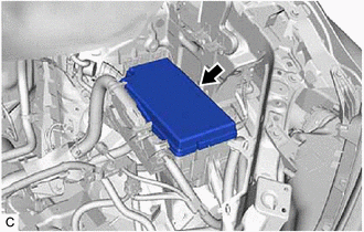
Remove the No. 1 relay block cover from the engine room relay block assembly.
-
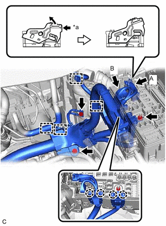
*a Push Pull up the lock lever and disconnect the connector (A).
-
Disconnect the connector (B) from the engine room relay block assembly.
-
Remove the nut from the engine room relay block assembly.
-
Using a screwdriver, disengage the 4 claws and separate the engine wire from the engine room relay block assembly.
-
Disengage the 4 clamps.
-
Remove the 2 bolts to disconnect the engine wire.
-
Disengage the clamp to disconnect the No. 2 engine wire from the bracket.
-
Disengage the clamp from the continuously variable transaxle assembly.
-
Remove the bolt and disconnect the No. 3 engine wire from the continuously variable transaxle assembly.
-
-
REMOVE STARTER ASSEMBLY
-
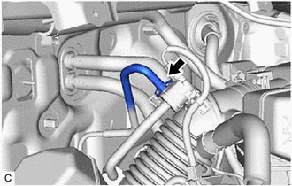
DISCONNECT FUEL TUBE SUB-ASSEMBLY
-
SEPARATE UNION TO CHECK VALVE HOSE
-
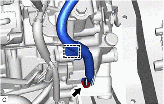
DISCONNECT NO. 1 FUEL VAPOR FEED HOSE
-
Slide the clip and disconnect the No. 1 fuel vapor feed hose from the No. 1 vacuum switching valve assembly.
-
-
REMOVE AIR CLEANER HOSE ASSEMBLY
-
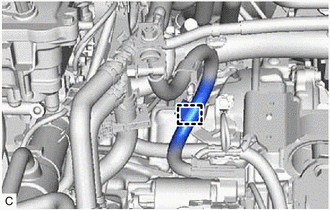
DISCONNECT BREATHER PLUG HOSE
-
Disconnect the breather plug hose from the clamp.
-
-
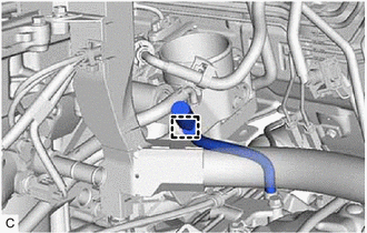
DISCONNECT TRANSMISSION CONTROL CABLE ASSEMBLY
-
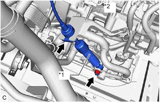
*1 Transmission Control Cable Assembly *2 No. 1 Transmission Control Cable Bracket Remove the nut and disconnect the transmission control cable assembly from the control shaft lever.
-
Remove the clip and disconnect the transmission control cable assembly from the No. 1 transmission control cable bracket.
-
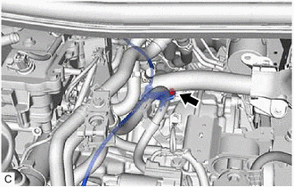
Remove the bolt and disconnect the transmission control cable assembly with the transmission control cable support from the continuously variable transaxle assembly.
-
-
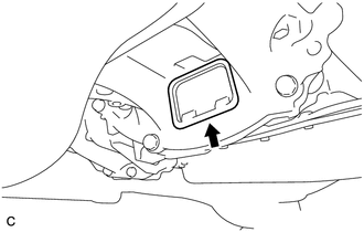
REMOVE COLUMN HOLE COVER SILENCER SHEET
-
SEPARATE NO. 2 STEERING INTERMEDIATE SHAFT ASSEMBLY
-
SEPARATE NO. 1 STEERING COLUMN HOLE COVER SUB-ASSEMBLY
-
REMOVE FRONT EXHAUST PIPE ASSEMBLY (TWC: Rear Catalyst)
-
REMOVE FRONT DRIVE SHAFT ASSEMBLY
-
REMOVE FRONT SUSPENSION MEMBER REINFORCEMENT LH
-
REMOVE FRONT SUSPENSION MEMBER REINFORCEMENT RH
Tech Tips
Use the same procedure as for the LH side.
-
REMOVE FLYWHEEL HOUSING UNDER COVER
-
Remove the flywheel housing under cover from the stiffening crankcase assembly.
-
-
REMOVE DRIVE PLATE AND TORQUE CONVERTER ASSEMBLY SETTING BOLT
-
REMOVE FRONT SUSPENSION MEMBER BRACE SUB-ASSEMBLY LH
-
REMOVE FRONT SUSPENSION MEMBER BRACE SUB-ASSEMBLY RH
Tech Tips
Use the same procedure as for the LH side.
-
REMOVE FRONT SUSPENSION CROSSMEMBER SUB-ASSEMBLY
-
REMOVE ENGINE ASSEMBLY WITH TRANSAXLE
-
Set the engine assembly with transaxle on an engine lifter.
Note
-
Using height adjustment attachments and plate lift attachments, keep the engine assembly with transaxle horizontal.
-
Do not position the height adjustment attachments or plate lift attachments under the front cross member sub-assembly.
-
Do not perform any procedures while the engine assembly is suspended because doing so may cause the engine assembly to drop, resulting in injury. However, the engine assembly needs to be suspended when it is installed to or removed from an engine stand.
-
To prevent the engine assembly from unexpectedly moving, securely support the engine assembly until it is secured to an engine stand.
-
To prevent the oil pan sub-assembly from deforming, do not place any attachments under the oil pan sub-assembly of the engine assembly with transaxle.
-
-
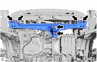
Remove the 6 bolts and front crossmember sub-assembly.
-
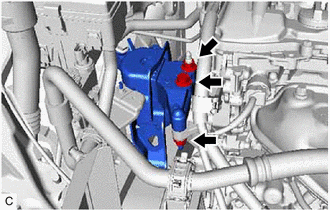
Remove the bolt and 2 nuts and separate the engine mounting insulator sub-assembly RH from the engine mounting bracket RH.
-
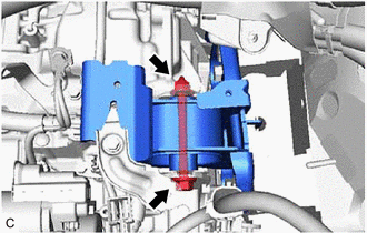
Remove the bolt and nut and separate the engine mounting insulator LH from the engine mounting bracket LH.
-
Operate the engine lifter and remove the engine assembly with transaxle from the vehicle.
Note
-
Make sure that the engine assembly with transaxle is clear of all wiring and hoses.
-
While lowering the engine assembly with transaxle from the vehicle, do not allow it to contact the vehicle.
-
-
-
INSTALL ENGINE HANGER
-
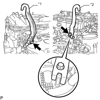
*1 No. 1 Engine Hanger *2 No. 2 Engine Hanger Install the No. 1 engine hanger and No. 2 engine hanger with the 2 bolts as shown in the illustration.
- Torque:
- 43 N*m { 438 kgf*cm, 32 ft.*lbf }
Tech Tips
No. 1 Engine Hanger 12281-0V010 No. 2 Engine Hanger 12282-0V030 Bolt (No. 1 Engine Hanger) 91552-81040
90105-C0170
Bolt (No. 2 Engine Hanger) 91552-81025
90105-C0169
-
Using an engine sling device and engine lift, secure the engine assembly with transaxle.
Note
-
Pay attention to the angle of the sling device as the engine assembly or No. 1 engine hanger and No. 2 engine hanger may be damaged or deformed if the angle is incorrect.
-
Do not perform any procedures while the engine assembly is suspended because doing so may cause the engine assembly to drop, resulting in injury. However, the engine assembly needs to be suspended when it is installed to or removed from an engine stand.
-
-
-
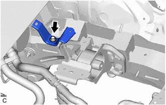
REMOVE FRONT ENGINE MOUNTING INSULATOR
-
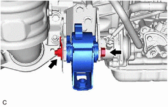
Remove the bolt, nut and front engine mounting insulator from the front engine mounting bracket.
Note
While holding the nut in place, loosen the bolt.
-
-
REMOVE FRONT ENGINE MOUNTING BRACKET
-
REMOVE REAR ENGINE MOUNTING INSULATOR
Tech Tips
Perform this procedure only when replacement of the rear engine mounting insulator is necessary.
-
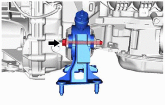
Remove the bolt and rear engine mounting insulator from the rear engine mounting bracket.
-
-
DISCONNECT ENGINE WIRE
-
REMOVE CONTINUOUSLY VARIABLE TRANSAXLE ASSEMBLY
-
REMOVE DRIVE PLATE AND RING GEAR SUB-ASSEMBLY
-
REMOVE ENGINE WIRE
-
Remove the engine wire from the engine assembly.
-
-
INSTALL ENGINE ASSEMBLY TO ENGINE STAND
-
Install the engine assembly to an engine stand.
-
Remove the 2 bolts, No. 1 engine hanger and No. 2 engine hanger.
-
-
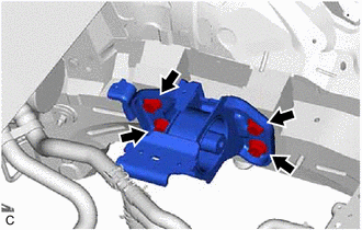
REMOVE ENGINE MOUNTING INSULATOR SUB-ASSEMBLY RH
Tech Tips
Perform this procedure only when replacement of the engine mounting insulator sub-assembly RH is necessary.
-
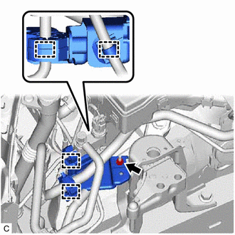
Disconnect the 4 clamps from the bracket.
-
Remove the nut and bracket from the engine mounting insulator sub-assembly RH.
-
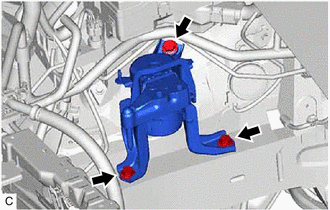
Remove the 3 bolts and engine mounting insulator sub-assembly RH.
-
-
REMOVE ENGINE MOUNTING INSULATOR LH
Tech Tips
Perform this procedure only when replacement of the engine mounting insulator LH is necessary.
-
Remove the bolt and bracket from the engine mounting insulator LH.
-
Remove the 4 bolts and engine mounting insulator LH.
-