RADIATOR INSTALLATION
PROCEDURE
-
INSTALL RADIATOR ASSEMBLY
-
Install the fan shroud assembly to the radiator assembly with the 2 bolts.
- Torque:
- 10.5 N*m { 107 kgf*cm, 8 ft.*lbf }
Note
Do not damage the radiator assembly when installing the fan shroud assembly.
-
*a Matchmark Align the matchmarks as shown in the illustration.
-
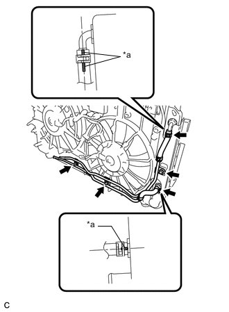
Connect the 2 oil cooler hoses to the radiator assembly and slide the 2 clips to secure them.
-
Install the oil cooler pipe with the 3 bolts.
- Torque:
- 5.5 N*m { 56 kgf*cm, 49 in.*lbf }
-
Install the 2 lower radiator supports.
-
Install the radiator assembly with the fan shroud assembly to the vehicle.
-
Connect the No. 3 air conditioner tube & accessory assembly to the fan shroud assembly with the bolt.
- Torque:
- 9.8 N*m { 100 kgf*cm, 87 in.*lbf }
-
-
INSTALL NO. 1 COOLER CONDENSER CUSHION
-
INSTALL COOLER CONDENSER ASSEMBLY
-
CONNECT NO. 2 AIR CONDITIONER TUBE AND ACCESSORY ASSEMBLY
-
CONNECT NO. 3 AIR CONDITIONER TUBE AND ACCESSORY ASSEMBLY
-
INSTALL NO. 2 FAN SHROUD
-
Engage the 2 claws.
-
Install the No. 2 fan shroud to the radiator assembly with the 2 bolts.
- Torque:
- 10.5 N*m { 107 kgf*cm, 8 ft.*lbf }
-
-
INSTALL UPPER RADIATOR SUPPORT SUB-ASSEMBLY
-
Install the 2 radiator support cushions.
-
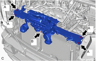
Install the upper radiator support sub-assembly with the 5 bolts.
- Torque:
- Bolt (A)
- 30 N*m { 306 kgf*cm, 22 ft.*lbf }
- Bolt (B)
- 8.5 N*m { 87 kgf*cm, 75 in.*lbf }
-
Engage the clamp and connect the hood lock control cable assembly to the upper radiator support sub-assembly.
-
Engage the 5 clamps and connect the wire harness to the upper radiator support sub-assembly and fan shroud assembly.
-
Connect the cooling fan motor connector and No. 2 cooling fan motor connector.
-
Engage the 5 clamps and connect the wire harness to the upper radiator support sub-assembly.
-
Connect the 2 horn connectors.
-
Engage the clamp and connect the No. 1 cooler refrigerant suction hose to the bracket.
-
-
INSTALL WATER BY-PASS PIPE SUB-ASSEMBLY
-
Install the water by-pass pipe sub-assembly to the upper radiator support sub-assembly with the 2 bolts.
- Torque:
- 12 N*m { 122 kgf*cm, 9 ft.*lbf }
-
-
CONNECT NO. 3 WATER BY-PASS HOSE
-
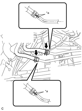
Connect the No. 3 water by-pass hose to the radiator assembly and slide the clip to secure it.
-
-
CONNECT NO. 2 WATER BY-PASS HOSE
-
Connect the No. 2 water by-pass hose to the radiator assembly and slide the clip to secure it.
-
-
CONNECT OIL COOLER HOSE
-
*a Matchmark Align the matchmarks as shown in the illustration.
-
Connect the 2 oil cooler hoses to the oil cooler pipe and slide the 2 clips to secure them.
-
-
CONNECT NO. 2 RADIATOR HOSE
-
Connect the No. 2 radiator hose to the radiator assembly and slide the clip to secure it.
-
-
CONNECT NO. 1 RADIATOR HOSE
-
Connect the No. 1 radiator hose to the radiator assembly and slide the clip to secure it.
-
Engage the clamp and connect the No. 1 radiator hose to the radiator hose clamp.
-
-
INSTALL FRONT NO. 2 BUMPER SIDE SEAL RH (for ALPHARD)
-
Engage the 2 claws.
-
Install the front No. 2 bumper side seal RH with the clip.
-
-
INSTALL FRONT NO. 2 BUMPER SIDE SEAL RH (for VELLFIRE)
-
Engage the 2 claws.
-
Install the front No. 2 bumper side seal RH with the clip.
-
-
INSTALL FRONT NO. 2 BUMPER SIDE SEAL LH (for ALPHARD)
-
Engage the 2 claws.
-
Install the front No. 2 bumper side seal LH with the clip.
-
-
INSTALL FRONT NO. 2 BUMPER SIDE SEAL LH (for VELLFIRE)
-
Engage the 2 claws.
-
Install the front No. 2 bumper side seal LH with the clip.
-
-
INSTALL HOOD LOCK ASSEMBLY
for LHD: Click here
for RHD: Click here
-
INSTALL INLET NO. 1 AIR CLEANER
-
INSTALL FRONT BUMPER ASSEMBLY (for ALPHARD)
-
INSTALL FRONT BUMPER ASSEMBLY (for VELLFIRE)
-
INSTALL BATTERY
-
INSTALL CENTER NO. 1 COWL TOP VENTILATOR LOUVER
-
CONNECT CABLE TO NEGATIVE BATTERY TERMINAL
Note
When disconnecting the cable, some systems need to be initialized after the cable is reconnected.
-
ADD ENGINE COOLANT
-
CHARGE AIR CONDITIONING SYSTEM WITH REFRIGERANT
-
INSPECT FOR COOLANT LEAK
-
WARM UP ENGINE
-
INSPECT FOR REFRIGERANT LEAK
-
INSTALL V-BANK COVER SUB-ASSEMBLY
-
INSTALL NO. 1 ENGINE UNDER COVER
-
Install the No. 1 engine under cover with the 8 bolts and 5 clips.
-