COOLING FAN SYSTEM Cooling Fan Circuit
DESCRIPTION
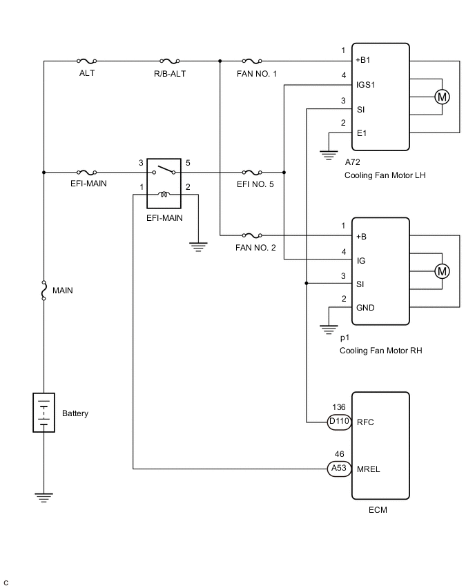
The ECM calculates an appropriate cooling fan speed based on the engine coolant temperature, air conditioning switch status, refrigerant pressure, engine speed and vehicle speed, and sends a signal to the cooling fan ECUs (cooling fan motors). The cooling fan ECUs (cooling fan motors) steplessly control the speed of the cooling fans based on the duty cycle signal sent from the ECM. By sending signals to the cooling fan ECUs (cooling fan motors) in accordance with the driving conditions and by controlling the cooling fan speed optimally with the ECM, both high cooling performance and quietness are ensured.
WIRING DIAGRAM
CAUTION / NOTICE / HINT
Note
-
Inspect the fuses for circuits related to this system before performing the following procedure.
-
Make sure to perform the necessary procedures (adjustment, calibration, initialization, or registration) after parts related to the cooling fan system have been removed/installed or replaced.
PROCEDURE
-
CHECK COOLING FAN SYSTEM
-
Disconnect the D110 ECM connector.
-
Turn the engine switch on (IG).
-
Check the operation of the cooling fans.
OK The cooling fans operate. Result Result Proceed to OK A NG (fan LH does not operate) B NG (fan RH does not operate) C NG (fans do not operate) D
B 
CHECK HARNESS AND CONNECTOR (COOLING FAN MOTOR LH - BODY GROUND) Click here
C
CHECK HARNESS AND CONNECTOR (COOLING FAN MOTOR RH - BODY GROUND) Click here
D
CHECK HARNESS AND CONNECTOR (COOLING FAN MOTOR LH AND COOLING FAN MOTOR RH POWER SOURCE) Click here
A 
-
-
PERFORM ACTIVE TEST USING GTS (CONTROL THE ENGINE COOLING FAN DUTY RATIO)
-
Connect the GTS to the DLC3.
-
Turn the engine switch on (IG).
-
Turn the GTS on.
-
Enter the following menus: Powertrain / Engine / Active Test / Control the Engine Cooling Fan Duty Ratio.
Powertrain > Engine > Active TestTester Display Control the Engine Cooling Fan Duty Ratio -
Check the operation of the cooling fans while operating them using the GTS.
OK Tester Operation Fan Operation 30 - 100% Cooling fans operate 0% Cooling fans stop Result Result Proceed to OK A NG (fans do not operate) B NG (fan LH does not stop) C NG (fan RH fan does not stop) D NG (fans do not stop) E
A 
PROCEED TO NEXT SUSPECTED AREA SHOWN IN PROBLEM SYMPTOMS TABLE Click here
B
REPLACE ECM Click here
D
CHECK HARNESS AND CONNECTOR (COOLING FAN MOTOR RH - ECM) Click here
E
CHECK HARNESS AND CONNECTOR (COOLING FAN MOTOR LH OR COOLING FAN MOTOR RH - ECM) Click here
C
-
-
CHECK HARNESS AND CONNECTOR (COOLING FAN MOTOR LH - ECM)
-
Disconnect the A72 cooling fan motor LH connector.
-
Disconnect the D110 ECM connector.
-
Measure the resistance according to the value(s) in the table below.
Standard Resistance Tester Connection Condition Specified Condition A72-3 (SI) - D110-136 (RFC) Always Below 1 Ω Result Proceed to OK NG
OK
REPLACE COOLING FAN MOTOR LH Click here
NG
REPAIR OR REPLACE HARNESS OR CONNECTOR
-
-
CHECK HARNESS AND CONNECTOR (COOLING FAN MOTOR RH - ECM)
-
Disconnect the p1 cooling fan motor RH connector.
-
Disconnect the D110 ECM connector.
-
Measure the resistance according to the value(s) in the table below.
Standard Resistance Tester Connection Condition Specified Condition p1-3 (SI) - D110-136 (RFC) Always Below 1 Ω Result Proceed to OK NG
OK
REPLACE COOLING FAN MOTOR RH Click here
NG
REPAIR OR REPLACE HARNESS OR CONNECTOR
-
-
CHECK HARNESS AND CONNECTOR (COOLING FAN MOTOR LH OR COOLING FAN MOTOR RH - ECM)
-
Disconnect the A72 cooling fan motor LH connector.
-
Disconnect the p1 cooling fan motor RH connector.
-
Disconnect the D110 ECM connector.
-
Measure the resistance according to the value(s) in the table below.
Standard Resistance Tester Connection Condition Specified Condition A72-3 (SI) or p1-3 (SI) - D110-136 (RFC) Always Below 1 Ω Result Proceed to OK NG
OK
REPLACE ECM Click here
NG
REPAIR OR REPLACE HARNESS OR CONNECTOR
-
-
CHECK HARNESS AND CONNECTOR (COOLING FAN MOTOR LH - BODY GROUND)
-
Disconnect the A72 cooling fan motor LH connector.
-
Measure the resistance according to the value(s) in the table below.
Standard Resistance Tester Connection Condition Specified Condition A72-2 (E1) - Body ground Always Below 1 Ω Result Proceed to OK NG
NG
REPAIR OR REPLACE HARNESS OR CONNECTOR
OK
-
-
CHECK HARNESS AND CONNECTOR (COOLING FAN MOTOR LH POWER SOURCE)
-
Disconnect the A72 cooling fan motor LH connector.
-
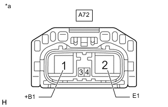
*a Front view of wire harness connector
(to Cooling Fan Motor LH)
Measure the voltage according to the value(s) in the table below.
Standard Voltage Tester Connection Condition Specified Condition A72-1 (+B1) - A72-2 (E1) Always 11 to 14 V Result Proceed to OK NG
NG
REPAIR OR REPLACE HARNESS OR CONNECTOR (COOLING FAN MOTOR LH - BATTERY)
OK
-
-
CHECK HARNESS AND CONNECTOR (COOLING FAN MOTOR LH POWER SOURCE)
-
Disconnect the A72 cooling fan motor LH connector.
-
Turn the engine switch on (IG).
-
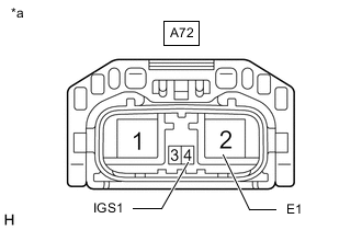
*a Front view of wire harness connector
(to Cooling Fan Motor LH)
Measure the voltage according to the value(s) in the table below.
Standard Voltage Tester Connection Condition Specified Condition A72-4 (IGS1) - A72-2 (E1) Engine switch on (IG) 11 to 14 V Result Proceed to OK NG
OK
REPLACE COOLING FAN MOTOR LH Click here
NG
REPAIR OR REPLACE HARNESS OR CONNECTOR (COOLING FAN MOTOR LH - EFI-MAIN RELAY)
-
-
CHECK HARNESS AND CONNECTOR (COOLING FAN MOTOR RH - BODY GROUND)
-
Disconnect the p1 cooling fan motor RH connector.
-
Measure the resistance according to the value(s) in the table below.
Standard Resistance Tester Connection Condition Specified Condition p1-2 (GND) - Body ground Always Below 1 Ω Result Proceed to OK NG
NG
REPAIR OR REPLACE HARNESS OR CONNECTOR
OK
-
-
CHECK HARNESS AND CONNECTOR (COOLING FAN MOTOR RH POWER SOURCE)
-
Disconnect the p1 cooling fan motor RH connector.
-
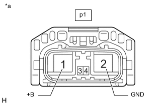
*a Front view of wire harness connector
(to Cooling Fan Motor RH)
Measure the voltage according to the value(s) in the table below.
Standard Voltage Tester Connection Condition Specified Condition p1-1 (+B) - p1-2 (GND) Always 11 to 14 V Result Proceed to OK NG
NG
REPAIR OR REPLACE HARNESS OR CONNECTOR (COOLING FAN MOTOR RH - BATTERY)
OK
-
-
CHECK HARNESS AND CONNECTOR (COOLING FAN MOTOR RH POWER SOURCE)
-
Disconnect the p1 cooling fan motor RH connector.
-
Turn the engine switch on (IG).
-
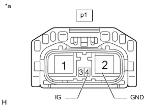
*a Front view of wire harness connector
(to Cooling Fan Motor RH)
Measure the voltage according to the value(s) in the table below.
Standard Voltage Tester Connection Condition Specified Condition p1-4 (IG) - p1-2 (GND) Engine switch on (IG) 11 to 14 V Result Proceed to OK NG
OK
REPLACE COOLING FAN MOTOR RH Click here
NG
REPAIR OR REPLACE HARNESS OR CONNECTOR (COOLING FAN MOTOR RH - EFI-MAIN RELAY)
-
-
CHECK HARNESS AND CONNECTOR (COOLING FAN MOTOR LH AND COOLING FAN MOTOR RH POWER SOURCE)
-
Disconnect the A72 cooling fan motor LH connector.
-
Disconnect the p1 cooling fan motor RH connector.
-
Turn the engine switch on (IG).
-
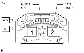
*1 Cooling Fan Motor LH *2 Cooling Fan Motor RH *a Front view of wire harness connector
(to Cooling Fan Motor LH and Cooling Fan Motor RH)
Measure the voltage according to the value(s) in the table below.
Standard Voltage Tester Connection Condition Specified Condition A72-4 (IGS1) - A72-2 (E1) Engine switch on (IG) 11 to 14 V p1-4 (IG) - p1-2 (GND) Engine switch on (IG) 11 to 14 V Result Proceed to OK NG
NG
CHECK HARNESS AND CONNECTOR (COOLING FAN MOTOR LH OR COOLING FAN MOTOR RH - EFI-MAIN RELAY) Click here
OK
-
-
CHECK HARNESS AND CONNECTOR (COOLING FAN MOTOR LH OR COOLING FAN MOTOR RH - ECM)
-
Disconnect the A72 cooling fan motor LH connector.
-
Disconnect the p1 cooling fan motor RH connector.
-
Disconnect the D110 ECM connector.
-
Measure the resistance according to the value(s) in the table below.
Standard Resistance Tester Connection Condition Specified Condition A72-3 (SI), p1-3 (SI) or D110-136 (RFC) - Body ground Always 10 kΩ or higher Result Proceed to OK NG
OK
REPAIR OR REPLACE HARNESS OR CONNECTOR (COOLING FAN MOTOR LH AND COOLING FAN MOTOR RH - BATTERY)
NG
REPAIR OR REPLACE HARNESS OR CONNECTOR (COOLING FAN MOTOR LH AND COOLING FAN MOTOR RH - ECM)
-
-
CHECK HARNESS AND CONNECTOR (COOLING FAN MOTOR LH OR COOLING FAN MOTOR RH - EFI-MAIN RELAY)
-
Disconnect the A72 cooling fan motor LH connector.
-
Disconnect the p1 cooling fan motor RH connector.
-
Remove the EFI-MAIN relay, A/F relay and EFI-MAIN NO. 2 relay from the No. 1 engine room relay block assembly.
Tech Tips
Remove the A/F relay and EFI-MAIN NO. 2 relay connected between the checked terminals as the coil inside the relay influences the measurement value.
-
Measure the resistance according to the value(s) in the table below.
Standard Resistance Tester Connection Condition Specified Condition A72-4 (IGS1) or p1-4 (IG) - 5 (EFI-MAIN relay) Always Below 1 Ω Result Result OK NG
OK
CHECK ECM POWER SOURCE CIRCUIT Click here
NG
REPAIR OR REPLACE HARNESS OR CONNECTOR
-