SFI SYSTEM Starter Signal Circuit
DESCRIPTION
When the engine switch is pushed (when engine start is permitted), the certification ECU (smart key ECU assembly) outputs voltage from terminal STAR (starter pinion operation signal) to the ST NO. 1 relay, via the park/neutral position switch assembly, to operate the starter pinion gear.
Then the starter delay circuit built into the engine stop and start ECU outputs voltage from terminal STA2 (starter motor operation signal) to the ST NO. 2 relay to operate the starter motor.
When the voltage output from terminal STA2 (starter motor operation signal) of the engine stop and start ECU is input to terminal STA of the ECM, the ECM determines that the engine is cranking, and begins engine control for engine start.
CAUTION / NOTICE / HINT
Note
-
Inspect the fuses for circuits related to this system before performing the following procedure.
-
When the starter assembly is replaced, the number of starter operations stored in the engine stop and start ECU must be reset.
-
When the starter assembly is replaced, "ST NO. 1 relay" and "ST NO. 2 relay" must be also replaced.
PROCEDURE
-
CHECK WHETHER ENGINE CAN BE CRANKED
-
Check if the engine can be cranked.
Result Result Proceed to Engine cannot be cranked A Engine can be cranked B
B 
READ VALUE USING GTS (STARTER SW) Click here
A 
-
-
READ VALUE USING GTS (STARTER SW)
-
Connect the GTS to the DLC3.
-
Turn the engine switch on (IG).
-
Turn the GTS on.
-
Enter the following menus: Powertrain / Engine / Data List / Starter SW.
Powertrain > Engine > Data ListTester Display Starter SW -
Check the value displayed on the GTS when the engine switch is turned on (IG) and the engine is cranked.
OK Condition GTS Display (Starter SW) Engine switch on (IG) OFF Cranking position ON Result Proceed to OK NG
NG
CHECK STOP AND START SYSTEM Click here
OK
-
-
INSPECT RELAY (ST NO. 2 RELAY)
-
Inspect the ST NO. 2 relay.
Result Proceed to OK NG
NG 
REPLACE RELAY (ST NO. 2 RELAY)
OK
-
-
INSPECT STARTER ASSEMBLY
-
Inspect the starter assembly.
Result Proceed to OK NG
NG
REPLACE STARTER ASSEMBLY Click here
OK
-
-
CHECK HARNESS AND CONNECTOR (ST NO. 2 RELAY - STARTER ASSEMBLY)
-
Remove the ST NO. 2 relay from the No. 1 engine room relay block.
-
Disconnect the starter assembly connector.
-
Measure the resistance according to the value(s) in the table below.
Standard Resistance Tester Connection Condition Specified Condition 3 (ST NO. 2 relay) - D82-1 (SL2) Always Below 1 Ω 3 (ST NO. 2 relay) or D82-1 (SL2) - Body ground and other terminals Always 10 kΩ or higher Result Proceed to OK NG
NG
REPAIR OR REPLACE HARNESS OR CONNECTOR
OK
-
-
CHECK HARNESS AND CONNECTOR (ST NO. 2 RELAY - ECM)
-
Remove the ST NO. 2 relay from the No. 1 engine room relay block.
-
Disconnect the engine stop and start ECU connector.
-
Disconnect the ECM connector.
-
Measure the resistance according to the value(s) in the table below.
Standard Resistance Tester Connection Condition Specified Condition 1 (ST NO. 2 relay) - A53-43 (STA) Always Below 1 Ω 1 (ST NO. 2 relay) or A53-43 (STA) - Body ground and other terminals Always 10 kΩ or higher Result Proceed to OK NG
NG
REPAIR OR REPLACE HARNESS OR CONNECTOR
OK
-
-
CHECK HARNESS AND CONNECTOR (ST NO. 2 RELAY - BODY GROUND)
-
Remove the ST NO. 2 relay from the No. 1 engine room relay block.
-
Measure the resistance according to the value(s) in the table below.
Standard Resistance Tester Connection Condition Specified Condition 2 (ST NO. 2 relay) - Body ground Always Below 1 Ω Result Proceed to OK NG
NG
REPAIR OR REPLACE HARNESS OR CONNECTOR
OK
-
-
CHECK TERMINAL VOLTAGE (POWER SOURCE OF ST NO. 2 RELAY)
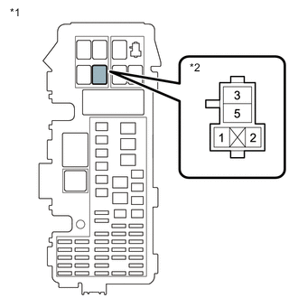
*1 No. 1 Engine Room Relay Block *2 ST NO. 2 Relay
-
Remove the ST NO. 2 relay from the No. 1 engine room relay block.
-
Measure the voltage according to the value(s) in the table below.
Standard Voltage Tester Connection Condition Specified Condition 5 (ST NO. 2 relay) - Body ground Always 11 to 14 V Result Proceed to OK NG
NG
REPAIR OR REPLACE HARNESS OR CONNECTOR (BATTERY - ST NO. 2 RELAY)
OK
-
-
INSPECT RELAY (ST NO. 1 RELAY)
-
Inspect the ST NO. 1 relay.
Result Proceed to OK NG
NG
REPLACE RELAY (ST NO. 1 RELAY)
OK
-
-
CHECK HARNESS AND CONNECTOR (ST NO. 1 RELAY - STARTER ASSEMBLY)
-
Remove the ST NO. 1 relay from the No. 1 engine room relay block.
-
Disconnect the starter assembly connector.
-
Measure the resistance according to the value(s) in the table below.
Standard Resistance Tester Connection Condition Specified Condition 3 (ST NO. 1 relay) - D82-2 (SL1) Always Below 1 Ω 3 (ST NO. 1 relay) or D82-2 (SL1) - Body ground and other terminals Always 10 kΩ or higher Result Proceed to OK NG
NG
REPAIR OR REPLACE HARNESS OR CONNECTOR
OK
-
-
CHECK HARNESS AND CONNECTOR (ST NO. 1 RELAY - BODY GROUND)
-
Remove the ST NO. 1 relay from the No. 1 engine room relay block.
-
Measure the resistance according to the value(s) in the table below.
Standard Resistance Tester Connection Condition Specified Condition 2 (ST NO. 1 relay) - Body ground Always Below 1 Ω Result Proceed to OK NG
NG
REPAIR OR REPLACE HARNESS OR CONNECTOR
OK
-
-
CHECK TERMINAL VOLTAGE (POWER SOURCE OF ST NO. 1 RELAY)
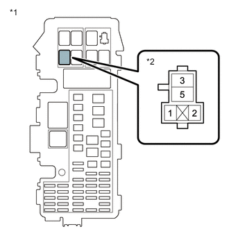
*1 No. 1 Engine Room Relay Block *2 ST NO. 1 Relay
-
Remove the ST NO. 1 relay from the No. 1 engine room relay block.
-
Measure the voltage according to the value(s) in the table below.
Standard Voltage Tester Connection Condition Specified Condition 5 (ST NO. 1 relay) - Body ground Always 11 to 14 V Result Proceed to OK NG
NG
REPAIR OR REPLACE HARNESS OR CONNECTOR (BATTERY - ST NO. 1 RELAY)
OK
-
-
CHECK HARNESS AND CONNECTOR (PARK/NEUTRAL POSITION SWITCH ASSEMBLY - ST NO. 1 RELAY)
-
Disconnect the park/neutral position switch assembly connector.
-
Remove the ST NO. 1 relay from the No. 1 engine room relay block.
-
Measure the resistance according to the value(s) in the table below.
Standard Resistance Tester Connection Condition Specified Condition D80-9 (L) - 1 (ST NO. 1 relay) Always Below 1 Ω Result Proceed to OK NG
OK
REPAIR OR REPLACE HARNESS OR CONNECTOR (BATTERY - STARTER ASSEMBLY)
NG
REPAIR OR REPLACE HARNESS OR CONNECTOR
-
-
CHECK STOP AND START SYSTEM
-
Check the stop and start system.
Result Proceed to OK NG
NG
REPLACE STOP AND START SYSTEM
OK
-
-
CHECK HARNESS AND CONNECTOR (ENGINE STOP AND START ECU - ECM - ST NO. 2 RELAY)
-
Disconnect the engine stop and start ECU connector.
-
Disconnect the ECM connector.
-
Remove the ST NO. 2 relay from the No. 1 engine room relay block.
-
Measure the resistance according to the value(s) in the table below.
Standard Resistance Tester Connection Condition Specified Condition A60-23 (STA2) - A53-43 (STA) Always Below 1 Ω A60-23 (STA2), A53-43 (STA) or 1 (ST NO. 2 relay) - Body ground and other terminals Always 10 kΩ or higher Result Proceed to OK NG
NG
REPAIR OR REPLACE HARNESS OR CONNECTOR
OK
-
-
INSPECT PARK/NEUTRAL POSITION SWITCH ASSEMBLY
-
Inspect the park/neutral position switch assembly.
Result Proceed to OK NG
NG
REPLACE PARK/NEUTRAL POSITION SWITCH ASSEMBLY Click here
OK
-
-
CHECK HARNESS AND CONNECTOR (PARK/NEUTRAL POSITION SWITCH ASSEMBLY - ENGINE STOP AND START ECU - ST NO. 1 RELAY - CERTIFICATION ECU)
-
Disconnect the park/neutral position switch assembly connector.
-
Disconnect the engine stop and start ECU connector.
-
Remove the ST NO. 1 relay from the No. 1 engine room relay block.
-
Disconnect the certification ECU (smart key ECU assembly) connector.
-
Measure the resistance according to the value(s) in the table below.
Standard Resistance Tester Connection Condition Specified Condition D80-9 (L) - A60-21 (STA) Always Below 1 Ω D80-9 (L) - A58-12 (STA) Always Below 1 Ω D80-9 (L), A60-21 (STA), 1 (ST NO. 1 relay) or A58-12 (STA) - Body ground and other terminals Always 10 kΩ or higher Result Proceed to OK NG
NG
REPAIR OR REPLACE HARNESS OR CONNECTOR
OK
-
-
CHECK HARNESS AND CONNECTOR (CERTIFICATION ECU (SMART KEY ECU ASSEMBLY) - PARK/NEUTRAL POSITION SWITCH ASSEMBLY - ECM - ENGINE STOP AND START ECU)
-
Disconnect the certification ECU (smart key ECU assembly) connector.
-
Disconnect the park/neutral position switch assembly connector.
-
Disconnect the ECM connector.
-
Disconnect the engine stop and start ECU connector.
-
Measure the resistance according to the value(s) in the table below.
Standard Resistance Tester Connection Condition Specified Condition A58-10 (STAR) - D80-4 (B) Always Below 1 Ω A58-10 (STAR) - D110-106 (NSW) Always Below 1 Ω A58-10 (STAR), D80-4 (B), D110-106 (NSW) or A60-17 (CLL) - Body ground and other terminals Always 10 kΩ or higher Result Proceed to OK NG
OK
GO TO SMART ENTRY AND START SYSTEM Click here
NG
REPAIR OR REPLACE HARNESS OR CONNECTOR
-
-
READ VALUE USING GTS (STARTER SW)
-
Connect the GTS to the DLC3.
-
Turn the engine switch on (IG).
-
Turn the GTS on.
-
Enter the following menus: Powertrain / Engine / Data List / Starter SW.
Powertrain > Engine > Data ListTester Display Starter SW -
Check the value displayed on the GTS when the engine switch is turned on (IG) and the engine is cranked.
OK Condition GTS Display (Starter SW) Engine switch on (IG) OFF Cranking position ON Result Proceed to OK NG
OK
PROCEED TO NEXT SUSPECTED AREA SHOWN IN PROBLEM SYMPTOMS TABLE Click here
NG
REPAIR OR REPLACE HARNESS OR CONNECTOR (ST NO. 2 RELAY - ECM)
-