THROTTLE BODY INSTALLATION
PROCEDURE
-
INSTALL THROTTLE BODY GASKET
-
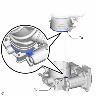
*a Protrusion Install a new throttle body gasket to the intake manifold with the protrusions of the throttle body gasket oriented as shown in the illustration.
-
-
INSTALL THROTTLE BODY WITH MOTOR ASSEMBLY
-
Connect the No. 1 water by-pass hose and No. 2 water by-pass hose to the throttle body with motor assembly and slide the 2 clips to secure them.
-
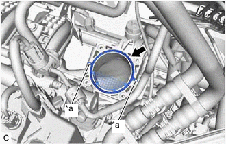
Install the throttle body with motor assembly to the intake manifold with the 4 bolts.
- Torque:
- 10 N*m { 102 kgf*cm, 7 ft.*lbf }
Note
If the throttle body with motor assembly has been struck or dropped, replace it.
-
Install the fuel hose bracket to the throttle body with motor assembly with the bolt.
- Torque:
- 10 N*m { 102 kgf*cm, 7 ft.*lbf }
-
Engage the fuel tube sub-assembly and breather plug hose to the fuel hose bracket.
-
Connect the throttle body with motor assembly connector.
-
-
INSTALL AIR CLEANER HOSE ASSEMBLY
-
*a Triangle Part *b Protrusion Install the air cleaner hose assembly to the throttle body with motor assembly as shown in the illustration.
Note
Align the triangle part of the air cleaner hose assembly with the protrusion of the throttle body with motor assembly.
-
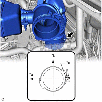
*a Front *b RH Side *c Stopper Tighten the hose clamp in the position shown in the illustration.
- Torque:
- 2.0 N*m { 20 kgf*cm, 18 in.*lbf }
-
Connect the ventilation hose to the cylinder head cover sub-assembly and slide the clip to secure it.
-
Engage the purge valve (purge VSV) to the air cleaner hose assembly.
-
Engage the No. 2 fuel vapor feed hose to the air cleaner hose assembly.
-
-
INSTALL AIR CLEANER CASE SUB-ASSEMBLY
-
Install the air cleaner case sub-assembly with the 3 bolts.
- Torque:
- 7.0 N*m { 71 kgf*cm, 62 in.*lbf }
-
Engage the clamp.
-
-
INSTALL AIR CLEANER CAP SUB-ASSEMBLY
-
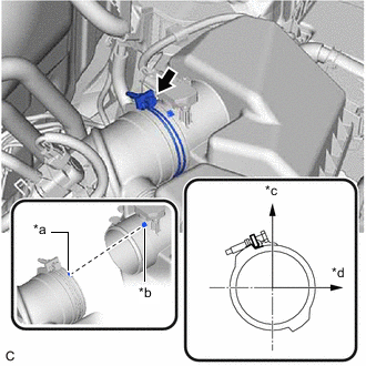
*a Cutout *b Protrusion *c Upper *d Front Install the air cleaner cap sub-assembly to the air cleaner hose assembly as shown in the illustration.
Note
Align the cutout of the air cleaner hose assembly with the protrusion of the air cleaner cap sub-assembly.
-
Tighten the hose clamp in the position shown in the illustration.
- Torque:
- 2.0 N*m { 20 kgf*cm, 1 ft.*lbf }
-
Engage the 2 guides to install the air cleaner cap sub-assembly to the air cleaner case sub-assembly.
-
Open the air cleaner cap sub-assembly and install the air cleaner filter element sub-assembly to the air cleaner case sub-assembly.
-
Engage the 2 air cleaner cap clamps.
-
Connect the mass air flow meter sub-assembly connector and engage the 2 wire harness clamps.
-
-
INSTALL BATTERY
-
CONNECT CABLE TO NEGATIVE BATTERY TERMINAL
Note
When disconnecting the cable, some systems need to be initialized after the cable is reconnected.
-
INSTALL CENTER NO. 1 COWL TOP VENTILATOR LOUVER
-
ADD ENGINE COOLANT
-
INSPECT FOR COOLANT LEAK
-
PERFORM INITIALIZATION
Note
-
Be sure to perform this procedure after removing and reinstalling the throttle body with motor assembly or any throttle body with motor assembly components.
-
Perform the following procedure after replacing the throttle body with motor assembly or any throttle body with motor assembly components. The following procedure should also be performed if the throttle body with motor assembly is cleaned.
-
Connect the GTS to the DLC3.
-
Clear the DTCs.
-
Perform the "Inspection After Repair".
-
Start the engine and check that the MIL is not illuminated. After the engine is warmed up, check that the idle speed is within the specified range with the A/C switch off.
Standard Idle Speed 700 to 800 rpm Note
-
Be sure to perform this step with all accessories off.
-
Make sure that the shift lever is in N or P.
-
-
Enter the following menus: Powertrain / Engine / Data List / Throttle Sensor Position.
Powertrain > Engine > Data ListTester Display Throttle Sensor Position -
Fully depress the accelerator pedal and check that the value is 60% or higher.
-
Perform a road test and confirm that there are no abnormalities.
-