WATER PUMP REMOVAL

PROCEDURE
-
REMOVE FRONT BUMPER ASSEMBLY (for ALPHARD)
-
REMOVE FRONT BUMPER ASSEMBLY (for VELLFIRE)
-
REMOVE V-RIBBED BELT
-
REMOVE V-BANK COVER SUB-ASSEMBLY
-
REMOVE WINDSHIELD WIPER MOTOR AND LINK ASSEMBLY
for LHD: Click here
for RHD: Click here
-
SEPARATE BRAKE MASTER CYLINDER RESERVOIR ASSEMBLY
for LHD: Click here
for RHD: Click here
-
REMOVE NO. 1 HEATER AIR DUCT SPLASH SHIELD SEAL
for LHD: Click here
for RHD: Click here
-
REMOVE NO. 2 HEATER AIR DUCT SPLASH SHIELD SEAL
for LHD: Click here
for RHD: Click here
-
REMOVE OUTER COWL TOP PANEL SUB-ASSEMBLY
for LHD: Click here
for RHD: Click here
-
REMOVE FRONT LOWER BUMPER ABSORBER
-
REMOVE NO. 1 ENGINE UNDER COVER
-
REMOVE FRONT SUSPENSION MEMBER REINFORCEMENT RH
-
REMOVE CRANKSHAFT PULLEY
-
DRAIN ENGINE COOLANT
-
REMOVE RADIATOR RESERVE TANK ASSEMBLY
-
REMOVE RADIATOR RESERVE TANK BRACKET
-
REMOVE NO. 2 ENGINE MOUNTING STAY RH
-
REMOVE ENGINE MOUNTING INSULATOR SUB-ASSEMBLY RH
-
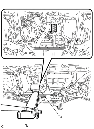
*a Wooden Block *b Jack 
Wooden Block Placement Location Place a wooden block between a jack and the engine.
Note
Make sure to set a jack as shown in the illustration. Do not place the jack under the oil pan.
-
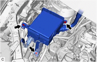
Remove the 3 bolts and separate the No. 2 engine room relay block assembly.
-
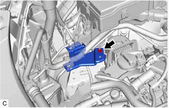
Remove the nut and cooler pipe bracket from the engine mounting insulator sub-assembly RH.
-
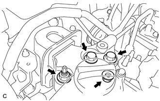
Remove the 2 bolts and 2 nuts and separate the engine mounting insulator sub-assembly RH from the front No. 1 engine mounting bracket LH.
Tech Tips
Remove any load from the bolts and nuts by adjusting the position of the jack when separating the engine mounting insulator sub-assembly RH from the front No. 1 engine mounting bracket LH.
-
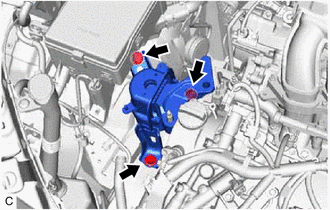
Remove the 3 bolts and engine mounting insulator sub-assembly RH.
-
-
REMOVE FRONT NO. 1 ENGINE MOUNTING BRACKET LH
-
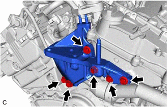
Remove the 6 bolts.
Tech Tips
There is not enough clearance to completely remove the bolt from the front No. 1 engine mounting bracket LH. Remove the front No. 1 engine mounting bracket LH together with the bolt.
-
Remove the front No. 1 engine mounting bracket LH together with the bolt.
-
-
REMOVE NO. 2 IDLER PULLEY SUB-ASSEMBLY
-
REMOVE V-RIBBED BELT TENSIONER PULLEY
-
Remove the 5 mm hexagon wrench.
-
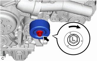
Remove the bolt, dust shield and V-ribbed belt tensioner pulley.
Note
-
Do not turn the bolt labeled "L" counterclockwise.
-
Store the V-ribbed belt tensioner pulley so that the bearing does not get damaged.
-
-
-
DISCONNECT NO. 2 RADIATOR HOSE
-
REMOVE WATER INLET HOUSING
-
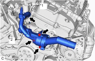
*1 Water By-pass Hose *2 Water Inlet Housing Slide the clip and disconnect the water by-pass hose.
-
Remove the 2 bolts, nut and water inlet housing.
-
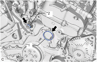
*1 No. 2 Water Inlet Housing Gasket *2 O-ring Remove the No. 2 water inlet housing gasket and O-ring.
-
-
REMOVE WATER PUMP PULLEY
-
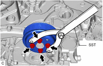
Using SST, hold the water pump pulley.
- SST
- 09960-10010 ( 09962-01000, 09963-00700 )
-
Remove the 4 bolts and separate the water pump pulley from the engine water pump assembly.
Tech Tips
There is not enough clearance to completely remove the water pump pulley from the water pump shaft. Remove the water pump pulley together with the engine water pump assembly.
-
-
REMOVE ENGINE WATER PUMP ASSEMBLY
-
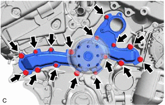
Remove the 16 bolts, engine water pump assembly, water pump pulley and water pump gasket.
-