RADIATOR REMOVAL
CAUTION / NOTICE / HINT
The necessary procedures (adjustment, calibration, initialization, or registration) that must be performed after parts are removed, installed, or replaced during the radiator assembly removal/installation are shown below.
| Replacement Part or Procedure | Necessary Procedures | Effects/Inoperative when not Performed | Link |
|---|---|---|---|
| Battery terminal is disconnected/reconnected | Drive the vehicle until stop and start control is permitted (approximately 15 to 40 minutes) | Stop and start system | |
| Memorize steering angle neutral point | Panoramic view monitor system | ||
| Initialize back door lock | Power door lock control system | ||
| Initialize servo motor | Air conditioning system | ||
| Reset slide door close position | Power slide door system | ||
| Reset back door close position | Power back door system | ||
| Removal/installtaion of the front television camera assembly or the radiator grille | Television camera view adjustment | Panoramic view monitor system |
PROCEDURE
-
PRECAUTION
Note
After turning the engine switch off, waiting time may be required before disconnecting the cable from the negative (-) battery terminal. Therefore, make sure to read the disconnecting the cable from the negative (-) battery terminal notices before proceeding with work.
-
DISCONNECT CABLE FROM NEGATIVE BATTERY TERMINAL
Note
When disconnecting the cable, some systems need to be initialized after the cable is reconnected.
-
RECOVER REFRIGERANT FROM REFRIGERATION SYSTEM
-
SEPARATE CENTER NO. 1 COWL TOP VENTILATOR LOUVER
-
REMOVE BATTERY
-
REMOVE FRONT BUMPER ASSEMBLY (for ALPHARD)
-
REMOVE FRONT BUMPER ASSEMBLY (for VELLFIRE)
-
REMOVE NO. 1 ENGINE UNDER COVER
-
Remove the 8 bolts, 5 clips and No. 1 engine under cover.
-
-
DRAIN ENGINE COOLANT
-
REMOVE INLET NO. 1 AIR CLEANER
-
REMOVE HOOD LOCK ASSEMBLY
-
REMOVE FRONT NO. 2 BUMPER SIDE SEAL LH (for ALPHARD)
-
Remove the clip.
-
Disengage the 2 claws and remove the front No. 2 bumper side seal LH.
-
-
REMOVE FRONT NO. 2 BUMPER SIDE SEAL LH (for VELLFIRE)
-
Remove the clip.
-
Disengage the 2 claws and remove the front No. 2 bumper side seal LH.
-
-
REMOVE FRONT NO. 2 BUMPER SIDE SEAL RH (for ALPHARD)
-
Remove the clip.
-
Disengage the 2 claws and remove the front No. 2 bumper side seal RH.
-
-
REMOVE FRONT NO. 2 BUMPER SIDE SEAL RH (for VELLFIRE)
-
Remove the clip.
-
Disengage the 2 claws and remove the front No. 2 bumper side seal RH.
-
-
DISCONNECT NO. 1 RADIATOR HOSE
-
Disengage the clamp and disconnect the No. 1 radiator hose from the radiator hose clamp.
-
Slide the clip and disconnect the No. 1 radiator hose from the radiator assembly.
-
-
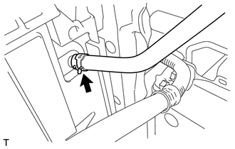
DISCONNECT NO. 2 RADIATOR HOSE
-
Slide the clip and disconnect the No. 2 radiator hose from the radiator assembly.
-
-
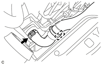
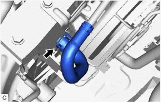
DISCONNECT NO. 2 WATER BY-PASS HOSE
-
Slide the clip and disconnect the No. 2 water by-pass hose from the radiator assembly.
-
-
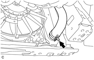
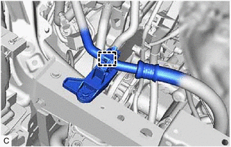
DISCONNECT NO. 3 WATER BY-PASS HOSE
-
Slide the clip and disconnect the No. 3 water by-pass hose from the radiator assembly.
-
-
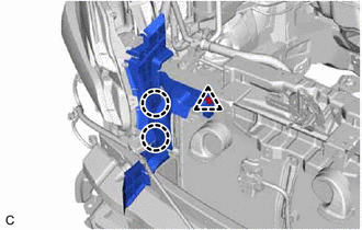
SEPARATE WATER BY-PASS PIPE SUB-ASSEMBLY
-
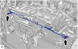
Remove the 2 bolts and separate the water by-pass pipe sub-assembly from the upper radiator support sub-assembly.
-
-
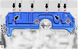
REMOVE UPPER RADIATOR SUPPORT SUB-ASSEMBLY
-
Disengage the clamp and disconnect the No. 1 cooler refrigerant suction hose from the bracket.
-
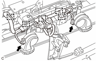
Disconnect the 2 horn connectors.
-
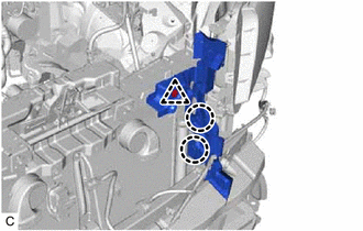
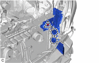
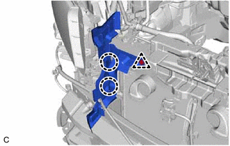
Disengage the 5 clamps and disconnect the wire harness from the upper radiator support sub-assembly.
-
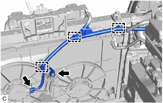
Disconnect the cooling fan motor connector and No. 2 cooling fan motor connector.
-
Disengage the 3 clamps and disconnect the wire harness from the upper radiator support sub-assembly and fan shroud assembly.
-
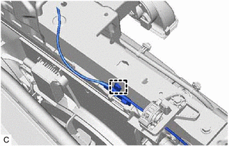
Disengage the clamp and disconnect the hood lock control cable assembly from the upper radiator support sub-assembly.
-
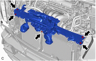
Remove the 5 bolts and upper radiator support sub-assembly.
-
Remove the 2 radiator support cushions.
-
-
REMOVE NO. 2 FAN SHROUD
-
Remove the 2 bolts.
-
Disengage the 2 claws and remove the No. 2 fan shroud from the radiator assembly.
-
-
DISCONNECT NO. 1 COOLER REFRIGERANT DISCHARGE HOSE
-
DISCONNECT NO. 2 AIR CONDITIONER TUBE AND ACCESSORY ASSEMBLY
-
REMOVE COOLER CONDENSER ASSEMBLY
-
REMOVE NO. 1 COOLER CONDENSER CUSHION
-
REMOVE RADIATOR ASSEMBLY
-
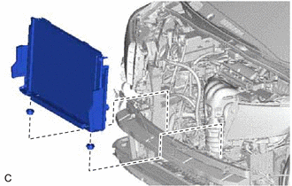
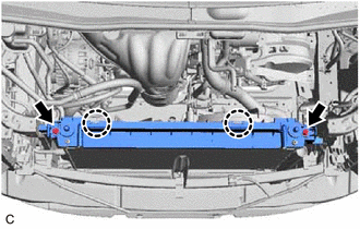
Remove the radiator assembly with the fan shroud assembly from the vehicle.
-
Remove the 2 lower radiator supports.
-
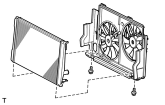
Remove the 2 bolts and fan shroud assembly from the radiator assembly.
Note
Do not damage the radiator assembly when removing the fan shroud assembly.
-