POWER MIRROR CONTROL SYSTEM(w/o Memory) TERMINALS OF ECU
-
CHECK MAIN BODY ECU (MULTIPLEX NETWORK BODY ECU), INSTRUMENT PANEL JUNCTION BLOCK ASSEMBLY
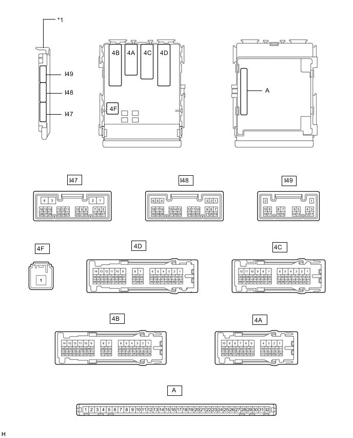
*1 Main Body ECU (Multiplex Network Body ECU) - -
-
Remove the main body ECU (multiplex network body ECU) from the instrument panel junction block assembly.
for LHD: Click here
for RHD: Click here
-
Measure the voltage and resistance according to the value(s) in the table below.
Tester Connection Wiring Color Terminal Description Condition Specified Condition 4F-1 - Body ground B - Body ground Power source Always 11 to 14 V A-32 (IG) - Body ground None - Body ground Power source (IG) Engine switch off → on (IG) Below 1 V → 11 to 14 V A-30 (ACC) - Body ground None - Body ground Power source (ACC) Engine switch off → on (ACC) Below 1 V → 11 to 14 V A-31 (BECU) - Body ground None - Body ground Power source Always 11 to 14 V A-11 (GND1) - Body ground None - Body ground Ground Always Below 1 Ω -
Install the main body ECU (multiplex network body ECU) to the instrument panel junction block assembly.
for LHD: Click here
for RHD: Click here
-
Measure the voltage according to the value(s) in the table below.
-
-
CHECK AIR CONDITIONING AMPLIFIER ASSEMBLY (w/ Mirror Heater)
-
CHECK AIR CONDITIONING CONTROL ASSEMBLY (w/ Mirror Heater)