POWER BACK DOOR SYSTEM Power Back Door cannot be Opened Using the Back Door Opener Switch
DESCRIPTION
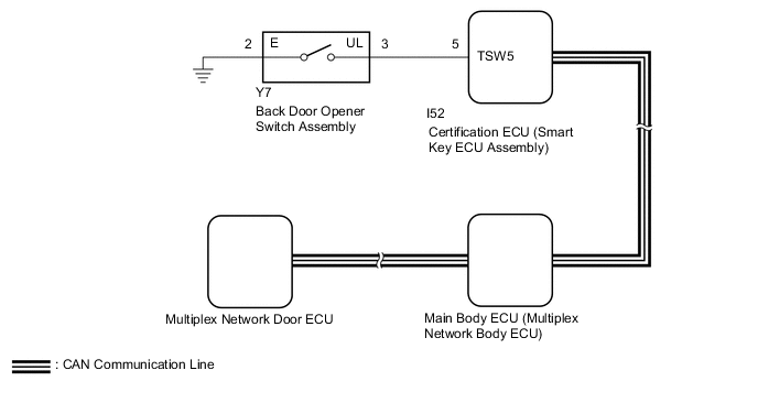
The multiplex network door ECU receives an open signal from the back door opener switch assembly via the certification ECU (smart key ECU assembly).
WIRING DIAGRAM
CAUTION / NOTICE / HINT
Note
-
First perform the communication function inspections in How to Proceed with Troubleshooting to confirm that there are no CAN communication malfunctions before troubleshooting this problem.
-
If the replacement, removal and installation of the multiplex network door ECU or disconnection of the connectors of the multiplex network door ECU has been performed, initialize the power back door system.
-
If the main body ECU (multiplex network body ECU) or certification ECU (smart key ECU assembly) is replaced, refer to Service Bulletin.
-
The power back door system troubleshooting procedure is based on the premise that the entry and start system (for Entry Function) is operating normally. Check the power back door system first before troubleshooting the power back door system.
-
As the door control battery is installed between the vehicle battery and main body ECU (multiplex network body ECU), first perform the inspections in On-Vehicle Inspection to confirm that there are no malfunctions in the power source circuit for the main body ECU (multiplex network body ECU) before performing this troubleshooting procedure.*
-
*: w/ Door Control Battery
PROCEDURE
-
READ VALUE USING GTS
-
Read the Data List according to the display on the GTS.
Body Electrical > Entry&Start > Data ListTester Display Measurement Item Range Normal Condition Diagnostic Note Tr/B-Door Unlock SW Back door opener switch assembly (open switch) signal ON or OFF ON: Back door opener switch assembly (open switch) on
OFF: Back door opener switch assembly (open switch) off
-
Body Electrical > Entry&Start > Data ListTester Display Tr/B-Door Unlock SW OK On GTS screen, item changes between ON and OFF according to above chart. Result Proceed to OK NG
NG 
INSPECT BACK DOOR OPENER SWITCH ASSEMBLY Click here
OK 
-
-
REPLACE MULTIPLEX NETWORK DOOR ECU
-
Temporarily replace the multiplex network door ECU with a new or normally functioning one.
Result Proceed to NEXT
NEXT
-
-
INITIALIZE MULTIPLEX NETWORK DOOR ECU
-
Initialize the multiplex network door ECU.
Result Proceed to NEXT
NEXT
-
-
CHECK POWER BACK DOOR SYSTEM
-
Check power back door system operation.
OK Power back door system operates normally Result Result Proceed to OK A NG (for LHD) B NG (for RHD) C
A 
END (MULTIPLEX NETWORK DOOR ECU WAS DEFECTIVE)
B
REPLACE MAIN BODY ECU(MULTIPLEX NETWORK BODY ECU) Click here
C
REPLACE MAIN BODY ECU(MULTIPLEX NETWORK BODY ECU) Click here
-
-
INSPECT BACK DOOR OPENER SWITCH ASSEMBLY
-
Remove the back door opener switch assembly.
-
Inspect the back door opener switch assembly
Result Proceed to OK NG
NG
REPLACE BACK DOOR OPENER SWITCH ASSEMBLY Click here
OK
-
-
CHECK HARNESS AND CONNECTOR (BACK DOOR OPENER SWITCH ASSEMBLY - CERTIFICATION ECU [SMART KEY ECU ASSEMBLY])
-
Disconnect the Y7 back door opener switch assembly connector.
-
Disconnect the I52 certification ECU (smart key ECU assembly) connector.
-
Measure the resistance according to the value(s) in the table below.
Standard Resistance Tester Connection Condition Specified Condition Y7-3 (UL) - I52-5 (TSW5) Always Below 1 Ω Y7-2 (E) - Body ground Always Below 1 Ω Y7-3 (UL) or I52-5 (TSW5) - Body ground Always 10 kΩ or higher Result Proceed to OK NG
OK
REPLACE CERTIFICATION ECU (SMART KEY ECU ASSEMBLY)
NG
REPAIR OR REPLACE HARNESS OR CONNECTOR
-