POWER WINDOW REGULATOR MOTOR(for Rear Side) INSPECTION
PROCEDURE
-
INSPECT POWER WINDOW REGULATOR MOTOR ASSEMBLY LH
Note
-
Do not apply voltage to any terminals except terminals 1 and 2, to avoid damaging the pulse sensor inside the motor.
-
Reset the power window regulator motor (initialize the pulse sensor) after installing the power window regulator motor and regulator assembly to the door.
-
w/ Jam Protection Function:
-
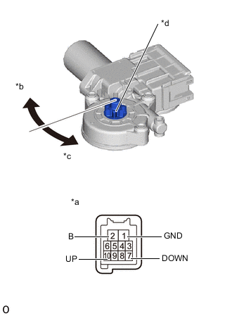
*a Component without harness connected
(Power Window Regulator Motor Assembly LH)
*b Clockwise *c Counterclockwise *d Motor Gear Apply positive (+) battery voltage to the connector terminal 2 (B).
-
Apply negative (-) battery voltage to the connector terminals 1 (GND) and 7 (DOWN) / 10 (UP).
-
Check that the motor gear rotates smoothly as follows.
OK Measurement Condition Specified Condition Battery positive (+) → 2 (B)
Battery negative (-): 1 (GND) (3 seconds or more) → 1 (GND) and 10 (UP) (within 1 second) → 1 (GND) (within 1 second) → 1 (GND) and 10 (UP)
Motor gear rotates clockwise (UP) Battery positive (+) → 2 (B)
Battery negative (-): 1 (GND) (3 seconds or more) → 1 (GND) and 7 (DOWN) (within 1 second) → 1 (GND) (within 1 second) → 1 (GND) and 7 (DOWN)
Motor gear rotates counterclockwise (DOWN)
-
-
-
INSPECT POWER WINDOW REGULATOR MOTOR ASSEMBLY RH
Note
-
Do not apply voltage to any terminals except terminals 1 and 2, to avoid damaging the pulse sensor inside the motor.
-
Reset the power window regulator motor (initialize the pulse sensor) after installing the power window regulator motor and regulator assembly to the door.
-
w/ Jam Protection Function:
-
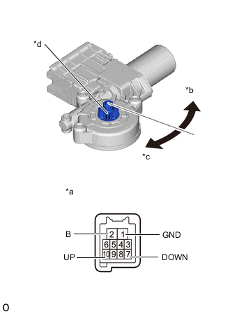
*a Component without harness connected
(Power Window Regulator Motor Assembly RH)
*b Counterclockwise *c Clockwise *d Motor Gear Apply positive (+) battery voltage to the connector terminal 2 (B).
-
Apply negative (-) battery voltage to the connector terminals 1 (GND) and 7 (DOWN) / 10 (UP).
-
Check that the motor gear rotates smoothly as follows.
OK Measurement Condition Specified Condition Battery positive (+) → 2 (B)
Battery negative (-): 1 (GND) (3 seconds or more) → 1 (GND) and 10 (UP) (within 1 second) → 1 (GND) (within 1 second) → 1 (GND) and 10 (UP)
Motor gear rotates clockwise (UP) Battery positive (+) → 2 (B)
Battery negative (-): 1 (GND) (3 seconds or more) → 1 (GND) and 7 (DOWN) (within 1 second) → 1 (GND) (within 1 second) → 1 (GND) and 7 (DOWN)
Motor gear rotates counterclockwise (DOWN)
-
-