ROOF HEADLINING INSTALLATION

CAUTION / NOTICE / HINT
Tech Tips
-
Use the same procedure for RHD and LHD vehicles.
-
The procedure listed below is for LHD vehicles.
-
A bolt without a torque specification is shown in the standard bolt chart.
PROCEDURE
-
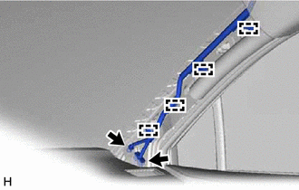
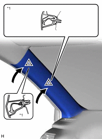
INSTALL REAR NO. 2 SIDE RAIL SPACER LH
-
Attach the 2 claws to install the rear No. 2 side rail spacer LH.
-
Install the 2 bolts.
-
-
INSTALL REAR NO. 2 SIDE RAIL SPACER RH
Tech Tips
Use the same procedure described for the LH side.
-
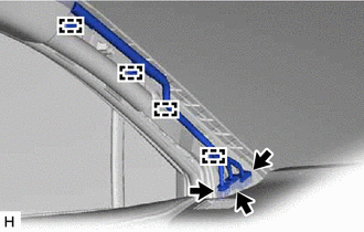
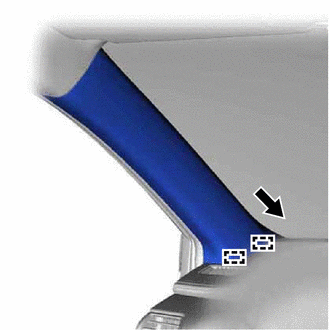
INSTALL REAR SIDE RAIL SPACER LH
-
Attach the claw to install the rear side rail spacer LH.
-
Install the 2 bolts.
-
-
INSTALL REAR SIDE RAIL SPACER RH
Tech Tips
Use the same procedure described for the LH side.
-
INSTALL CURTAIN SHIELD AIRBAG ASSEMBLY LH
-
INSTALL CURTAIN SHIELD AIRBAG ASSEMBLY RH
Tech Tips
Use the same procedure described for the LH side.
-
INSTALL FRONT SHOULDER BELT ANCHOR PLATE SUB-ASSEMBLY LH
-
Attach the 6 guides to install the front shoulder belt anchor plate sub-assembly LH.
-
-
INSTALL FRONT SHOULDER BELT ANCHOR PLATE SUB-ASSEMBLY RH
Tech Tips
Use the same procedure described for the LH side.
-
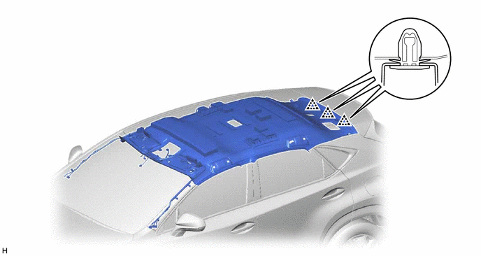
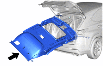
INSTALL ROOF HEADLINING ASSEMBLY (for Normal Roof)
-
for Type A:
-
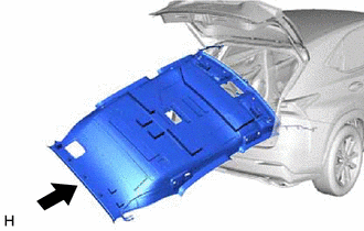
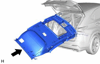
Insert the roof headlining assembly into the cabin from the back door.
Note
-
Check that the corners of the roof headlining are not folded, twisted or otherwise deformed and that none of the mounted parts have fallen off.
-
Make sure that the roof headlining does not get caught on anything as it may become bent or damaged.
-
Do not damage the roof headlining or vehicle interior.
-
-
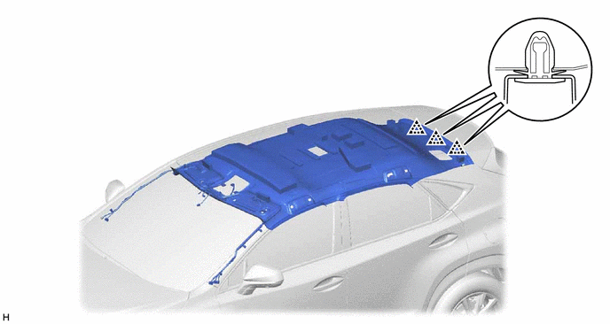
Attach the 3 clips to install the roof headlining assembly.
-
-
for Type B:
-
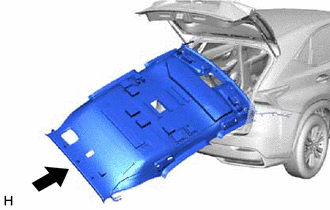
Insert the roof headlining assembly into the cabin from the back door.
Note
-
Check that the corners of the roof headlining are not folded, twisted or otherwise deformed and that none of the mounted parts have fallen off.
-
Make sure that the roof headlining does not get caught on anything as it may become bent or damaged.
-
Do not damage the roof headlining or vehicle interior.
-
-
Attach the 3 clips to install the roof headlining assembly.
-
-
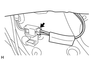
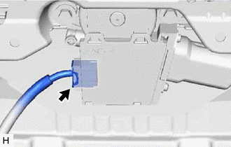
Connect the connector to the rear pillar RH.
-
for LHD:
-

*A w/ Rain Senseor w/ EC Mirror, w/o Lane Departure Alert System:
Connect the connectors.
-
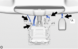
*A w/ Rain Senseor w/ EC Mirror, w/ Lane Departure Alert System:
Connect the connectors.
-
-
for RHD:
-

*A w/ Rain Senseor w/ EC Mirror, w/o Lane Departure Alert System:
Connect the connectors.
-
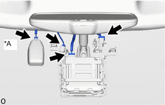
*A w/ Rain Senseor w/ EC Mirror, w/ Lane Departure Alert System:
Connect the connectors.
-
-
Connect the connectors and attach the clamps to the front pillar LH.
-
Connect the connectors and attach the clamps to the front pillar RH.
-
-
INSTALL ROOF HEADLINING ASSEMBLY (for Sliding Roof)
-
for Type A:
-
Insert the roof headlining assembly into the cabin from the back door.
Note
-
Check that the corners of the roof headlining are not folded, twisted or otherwise deformed and that none of the mounted parts have fallen off.
-
Make sure that the roof headlining does not get caught on anything as it may become bent or damaged.
-
Do not damage the roof headlining or vehicle interior.
-
-
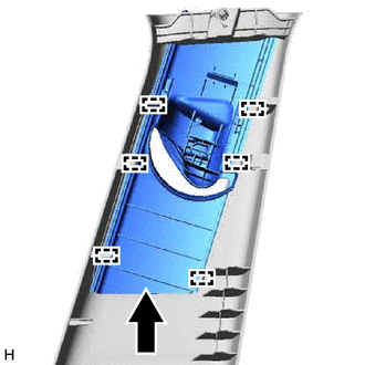
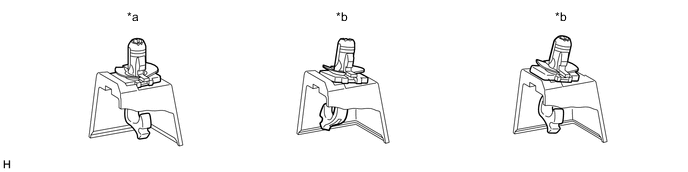
Attach the guide, 3 clips and 8 fasteners to install the roof headlining assembly.
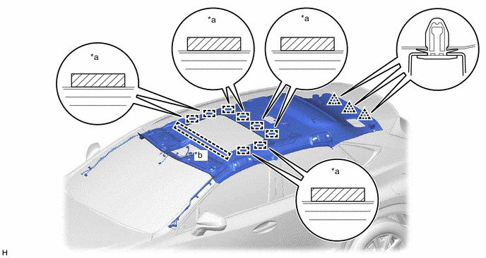
*a Guide *b Fastener
-
-
for Type B:
-
Insert the roof headlining assembly into the cabin from the back door.
Note
-
Check that the corners of the roof headlining are not folded, twisted or otherwise deformed and that none of the mounted parts have fallen off.
-
Make sure that the roof headlining does not get caught on anything as it may become bent or damaged.
-
Do not damage the roof headlining or vehicle interior.
-
-
Attach the guide, 3 clips and 8 fasteners to install the roof headlining assembly.
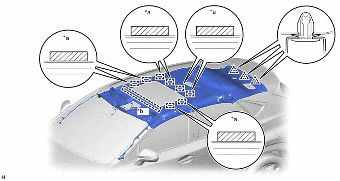
*a Guide *b Fastener
-
-
Connect the connector to the rear pillar RH.
-
for LHD:
-

*A w/ Rain Sensor w/ EC Mirror, w/o Lane Departure Alert System:
Connect the connectors.
-

*A w/ Rain Sensor w/ EC Mirror, w/ Lane Departure Alert System:
Connect the connectors.
-
-
for RHD:
-

*A w/ Rain Sensor w/ EC Mirror, w/o Lane Departure Alert System:
Connect the connectors.
-

*A w/ Rain Sensor w/ EC Mirror, w/ Lane Departure Alert System:
Connect the connectors.
-
-
Connect the drive gear connector.
-
Connect the connectors and attach the clamps to the front pillar LH.
-
Connect the connectors and attach the clamps to the front pillar RH.
-
-
INSTALL ROOF HEADLINING ASSEMBLY (for Glass Roof)
-
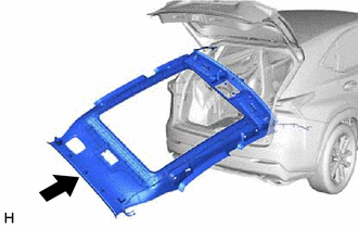
Insert the roof headlining assembly into the cabin from the back door.
Note
-
Check that the corners of the roof headlining are not folded, twisted or otherwise deformed and that none of the mounted parts have fallen off.
-
Make sure that the roof headlining does not get caught on anything as it may become bent or damaged.
-
Do not damage the roof headlining or vehicle interior.
-
-
Attach the guide, 3 clips and 14 fasteners to install the roof headlining assembly.
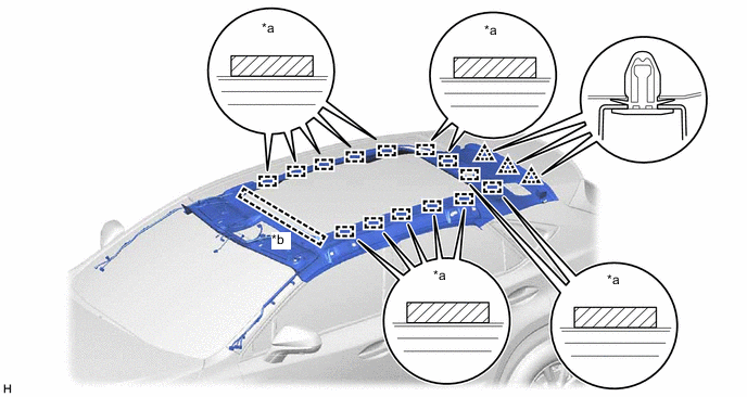
*a Guide *b Fastener -
Connect the connector to the rear pillar RH.
-
for LHD:
-
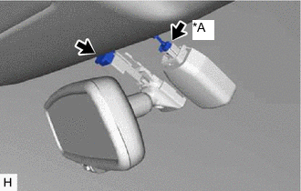
*A w/ Rain Sensor w/ EC Mirror, w/o Lane Departure Alert System:
Connect the connectors.
-

*A w/ Rain Sensor w/ EC Mirror, w/ Lane Departure Alert System:
Connect the connectors.
-
-
for RHD:
-
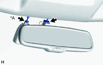
*A w/ Rain Sensor w/ EC Mirror, w/o Lane Departure Alert System:
Connect the connectors.
-
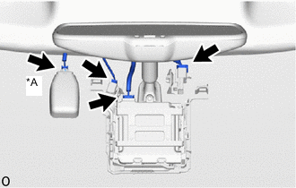
*A w/ Rain Sensor w/ EC Mirror, w/ Lane Departure Alert System:
Connect the connectors.
-
-
Connect the connectors and attach the clamps to the front pillar LH.
-
Connect the connectors and attach the clamps to the front pillar RH.
-
-
INSTALL INNER REAR VIEW MIRROR STAY HOLDER COVER (w/ EC Mirror, w/o Lane Departure Alert System)
-
INSTALL RAIN SENSOR COVER (w/ Rain Sensor)
-
INSTALL NO. 1 FORWARD RECOGNITION COVER (w/ EC Mirror, w/ Lane Departure Alert System)
-
INSTALL NO. 2 FORWARD RECOGNITION COVER (w/ EC Mirror, w/ Lane Departure Alert System)
-
INSTALL SEAT BELT ANCHOR COVER
-
Attach the 2 guides, 2 claws and 3 clips to install the seat belt anchor cover.
-
-
INSTALL SPOT LIGHT ASSEMBLY
-
INSTALL MAP LIGHT ASSEMBLY
-
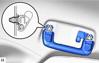
INSTALL ASSIST GRIP SUB-ASSEMBLY
Tech Tips
Use the same procedure for both assist grip sub-assemblies.
-
Install the 2 clips and 2 assist grip covers to the assist grip.
-
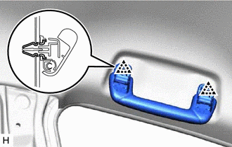
Attach the 2 clips to install the assist grip sub-assembly.
-
-
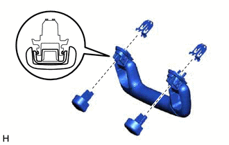
INSTALL REAR ASSIST GRIP ASSEMBLY LH
-
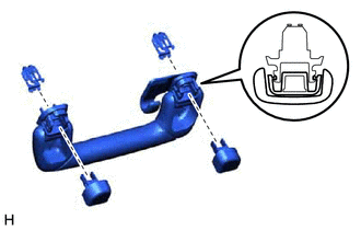
Install the 2 clips and 2 assist grip covers to the rear assist grip.
-
Attach the 2 clips to install the rear assist grip assembly LH.
-
-
INSTALL REAR ASSIST GRIP ASSEMBLY RH
Tech Tips
Use the same procedure described for the LH side.
-
INSTALL VISOR HOLDER
Tech Tips
Use the same procedure for both visor holders.
-
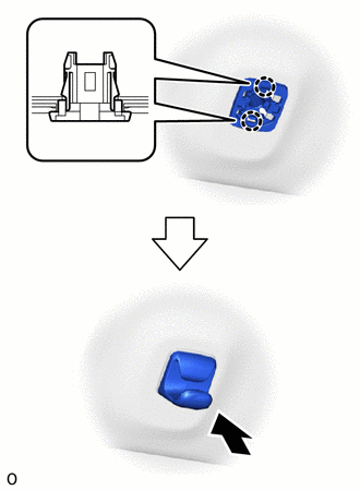
Attach the 2 claws.
-
Push in the visor holder to install it.
-
-
INSTALL VISOR ASSEMBLY LH
-
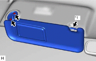
*1 Visor Holder Install the visor assembly LH with the 2 screws.
-
Connect the visor assembly LH to the visor holder.
-
-
INSTALL VISOR ASSEMBLY RH
Tech Tips
Use the same procedure described for the LH side.
-
INSTALL VISOR BRACKET COVER
Tech Tips
Use the same procedure for both visor bracket covers.
-
Attach the 4 claws to install the visor bracket cover.
-
-
INSTALL INNER ROOF SIDE GARNISH ASSEMBLY LH
-
Attach the 7 clips to install the inner roof side garnish assembly LH.
-
-
INSTALL INNER ROOF SIDE GARNISH ASSEMBLY RH
Tech Tips
Use the same procedure described for the LH side.
-
INSTALL DECK TRIM SIDE PANEL ASSEMBLY LH
-
Connect the connectors.
-
Attach the 2 guides, 2 clips and 5 claws to install the deck trim side panel assembly LH.
-
-
INSTALL DECK TRIM SIDE PANEL ASSEMBLY RH
Tech Tips
Use the same procedure described for the LH side.
-
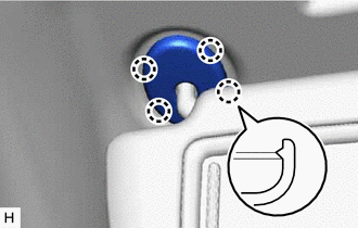
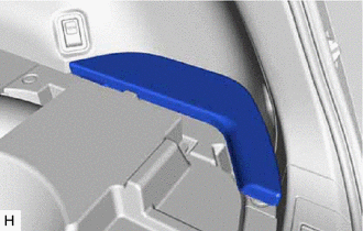
INSTALL NO. 1 LUGGAGE COMPARTMENT TRIM HOOK
-
for LH Side:
-
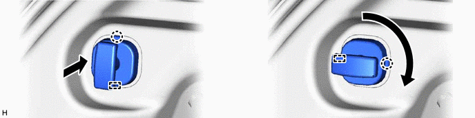
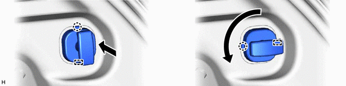
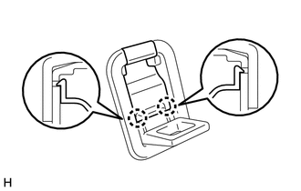
Turn the claw upward as shown in the illustration and insert the No. 1 luggage compartment trim hook.
-
Turn the No. 1 luggage compartment trim hook in the direction indicated by the arrow shown in the illustration and attach the claw and guide to install the No. 1 luggage compartment trim hook.
-
-
for RH Side:
-
Turn the claw upward as shown in the illustration and insert the No. 1 luggage compartment trim hook.
-
Turn the No. 1 luggage compartment trim hook in the direction indicated by the arrow shown in the illustration and attach the claw and guide to install the No. 1 luggage compartment trim hook.
-
-
-
INSTALL LUGGAGE HOLD BELT STRIKER ASSEMBLY
Tech Tips
Use the same procedure for all luggage hold belt striker assemblies.
-
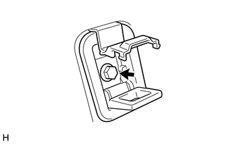
Install the luggage hold belt striker assembly with the bolt.
-
-
INSTALL ROPE HOOK ASSEMBLY
Tech Tips
Use the same procedure for both rope hook assemblies.
-
Install the rope hook assembly with the bolt.
-
Attach the 2 claws to close the cover.
-
-
INSTALL UPPER DECK TRIM SIDE BOARD LH
-
Attach the guide and 10 claws to install the upper deck trim side board LH.
-
Install the bolt.
-
-
INSTALL UPPER DECK TRIM SIDE BOARD RH
Tech Tips
Use the same procedure described for the LH side.
-
INSTALL NO. 3 BATTERY SERVICE COVER BOARD (for Power Seat)
-
INSTALL NO. 2 BATTERY SERVICE COVER BOARD (for Power Seat)
-
INSTALL CENTER PILLAR GARNISH ASSEMBLY LH
-
Pass the front seat outer belt floor anchor through the center pillar garnish assembly LH.
-
Attach the clip to install the center pillar garnish assembly LH.
-
Install the 2 clips.
-
-
INSTALL CENTER PILLAR GARNISH ASSEMBLY RH
Tech Tips
Use the same procedure described for the LH side.
-
INSTALL LOWER CENTER PILLAR GARNISH LH
-
Attach the 4 clips.
-
While pulling both sides of the lower center garnish LH outward by hand, set the lower center pillar garnish LH in place, and then attach the 2 claws to install the lower center pillar garnish LH.
-
-
INSTALL LOWER CENTER PILLAR GARNISH RH
Tech Tips
Use the same procedure described for the LH side.
-
CONNECT FRONT SEAT OUTER BELT ASSEMBLY LH
-
Connect the front seat outer belt assembly LH with the bolt.
- Torque:
- 42 N*m { 428 kgf*cm, 31 ft.*lbf }
-
-
CONNECT FRONT SEAT OUTER BELT ASSEMBLY RH
Tech Tips
Use the same procedure described for the LH side.
-
INSTALL OUTER LAP BELT ANCHOR COVER
Tech Tips
Use the same procedure for both outer lap belt anchor covers.
-
Attach the guide and 2 claws to install the outer lap belt anchor cover.
-
-
INSTALL FRONT PILLAR GARNISH ASSEMBLY LH
-
Install the front pillar garnish clips to the front pillar garnish LH.
Tech Tips
Install the front pillar garnish clips so that it faces as shown in the illustration.
*a CORRECT *b INCORRECT -
Attach the 2 guides.
-
*1 Front Pillar Garnish Clip Attach the 2 front pillar garnish clips to install the front pillar garnish assembly LH.
Tech Tips
Make sure that the curtain shield airbag assembly LH is not pinched.
-
-
INSTALL FRONT PILLAR GARNISH ASSEMBLY RH
Tech Tips
Use the same procedure described for the LH side.
-
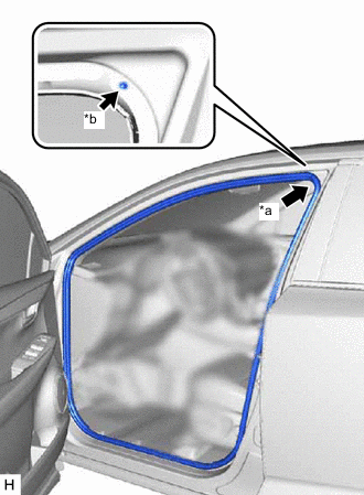
INSTALL REAR DOOR OPENING TRIM WEATHERSTRIP LH
-
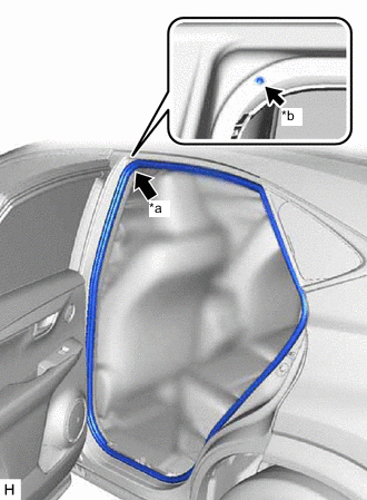
*a Paint Mark *b Mark Position Align the paint mark on the rear door opening trim weatherstrip LH with the mark position on the vehicle and install the rear door opening trim weatherstrip LH as shown in the illustration.
-
-
INSTALL REAR DOOR OPENING TRIM WEATHERSTRIP RH
Tech Tips
Use the same procedure described for the LH side.
-
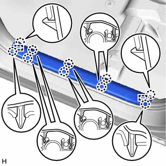
INSTALL REAR DOOR SCUFF PLATE LH
-
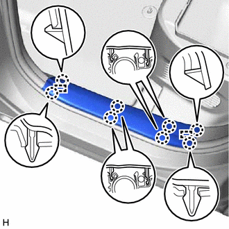
Attach the 2 guides and 8 claws to install the rear door scuff plate LH.
-
-
INSTALL REAR DOOR SCUFF PLATE RH
Tech Tips
Use the same procedure described for the LH side.
-
INSTALL FRONT DOOR OPENING TRIM WEATHERSTRIP LH
-
*a Paint Mark *b Mark Position Align the paint mark on the front door opening trim weatherstrip LH with the mark position on the vehicle and install the front door opening trim weatherstrip LH as shown in the illustration.
-
-
INSTALL FRONT DOOR OPENING TRIM WEATHERSTRIP RH
Tech Tips
Use the same procedure described for the LH side.
-
INSTALL COWL SIDE TRIM BOARD LH
-
Attach the clip to install the cowl side trim board LH.
-
Install the cap nut.
-
-
INSTALL COWL SIDE TRIM BOARD RH
Tech Tips
Use the same procedure described for the LH side.
-
INSTALL DOOR SCUFF PLATE ASSEMBLY LH
-
Attach the 2 guides and 10 claws to install the door scuff plate assembly LH.
-
-
INSTALL DOOR SCUFF PLATE ASSEMBLY RH
Tech Tips
Use the same procedure described for the LH side.
-
INSTALL REAR FLOOR FINISH PLATE
-
Attach the 4 claws and 4 clips to install the rear floor finish plate.
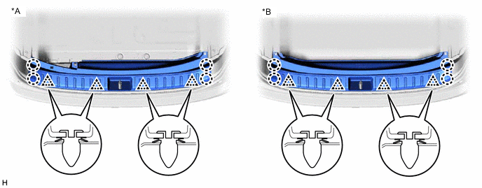
*A w/ Spare Tire *B w/o Spare Tire
-
-
INSTALL NO. 2 TOOL BOX SUB-ASSEMBLY (w/ Spare Tire)
-
Attach the 4 guides and 2 clips to install the No. 2 tool box sub-assembly.
-
Install the screw.
-
-
INSTALL NO. 2 TOOL BOX SUB-ASSEMBLY (w/o Spare Tire)
-
Attach the 4 guides and clip to install the No. 2 tool box sub-assembly.
-
Install the screw.
-
-
INSTALL NO. 1 TOOL BOX SUB-ASSEMBLY (w/ Spare Tire)
-
Attach the 5 guides, 2 claws and clip to install the No. 1 tool box sub-assembly.
-
Install the screw.
-
-
INSTALL NO. 1 TOOL BOX SUB-ASSEMBLY (w/o Spare Tire)
-
Attach the 4 guides, 4 claws and 2 clips to install the No. 1 tool box sub-assembly.
-
Install the screw.
-
-
INSTALL DECK FLOOR BOX LH (w/ Spare Tire)
-
Attach the 3 guides to install the deck floor box LH.
-
Install the 4 clips.
-
-
INSTALL DECK FLOOR BOX LH (w/o Spare Tire)
-
Attach the 4 guides to install the deck floor box LH.
-
Install the 2 clips.
-
-
INSTALL DECK FLOOR BOX RH (w/ Spare Tire)
-
Attach the 4 guides to install the deck floor box RH.
-
Install the 2 clips.
-
-
INSTALL DECK FLOOR BOX RH (w/o Spare Tire)
-
Attach the 4 guides to install the deck floor box RH.
-
Install the 2 clips.
-
-
INSTALL SPARE TIRE (w/ Spare Tire)
-
Install the spare tire.
-
-
INSTALL REAR DECK FLOOR BOX (w/ Spare Tire)
-
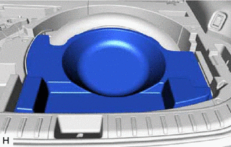
for Compact Size Spare Tire:
Install the rear deck floor box.
-
for Full Size Spare Tire:
Install the rear deck floor box.
-
-
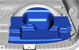
INSTALL NO. 3 DECK BOARD SUB-ASSEMBLY
-
w/o Spare Tire, for Compact Size Spare Tire:
Install the No. 3 deck board sub-assembly.
Tech Tips
Make sure part A shown in illustration faces the vehicle front.
-
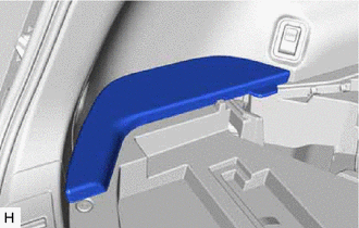
for Full Size Spare Tire:
Install the No. 3 deck board sub-assembly.
-
-
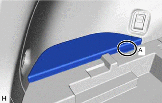
INSTALL NO. 2 DECK BOARD SUB-ASSEMBLY
-
w/o Spare Tire, for Compact Size Spare Tire:
Install the No. 2 deck board sub-assembly.
Tech Tips
Make sure part A shown in illustration faces the vehicle front.
-
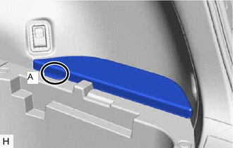
for Full Size Spare Tire:
Install the No. 2 deck board sub-assembly.
-
-
INSTALL DECK BOARD ASSEMBLY
-
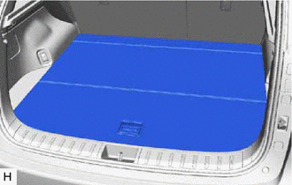
w/o Spare Tire, for Compact Size Spare Tire:
Install the deck board assembly.
-
for Full Size Spare Tire:
Install the deck board assembly.
-
-
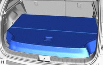
INSTALL TONNEAU COVER ASSEMBLY
-
Install the tonneau cover assembly.
-
-
INSTALL REAR SEAT ASSEMBLY (for Manual Seat)
-
INSTALL REAR SEAT ASSEMBLY (for Power Seat)
-
CONNECT CABLE TO NEGATIVE BATTERY TERMINAL
Note
When disconnecting the cable, some systems need to be initialized after the cable is reconnected.
-
CHECK SRS WARNING LIGHT
-
INSPECT SEAT HEATER SYSTEM (for Rear Seat, w/ Seat Heater System)