CONDENSER(for 3ZR-FAE) INSTALLATION
PROCEDURE
-
INSTALL COOLER CONDENSER ASSEMBLY
-
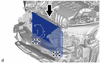
Attach the 2 guides to install the cooler condenser assembly.
Note
Do not damage the condenser assembly or radiator assembly when installing the condenser assembly.
-
-
CONNECT LIQUID PIPE SUB-ASSEMBLY
-
Remove the vinyl tape from the liquid pipe sub-assembly and the connecting part of the cooler condenser assembly.
-
Sufficiently apply compressor oil to a new O-ring and the fitting surface of the liquid pipe sub-assembly.
Compressor Oil ND-OIL 8 or equivalent -
Install the O-ring to the liquid pipe sub-assembly.
Note
Keep the O-rings and O-ring fitting surfaces free of foreign matter.
-
Connect the liquid pipe sub-assembly to the cooler condenser assembly with the bolt.
- Torque:
- 5.4 N*m { 55 kgf*cm, 48 in.*lbf }
-
-
CONNECT DISCHARGE HOSE SUB-ASSEMBLY
-
Remove the vinyl tape from the discharge hose sub-assembly and the connecting part of the cooler condenser assembly.
-
Sufficiently apply compressor oil to a new O-ring and the fitting surface of the discharge hose sub-assembly.
Compressor Oil ND-OIL 8 or equivalent -
Install the O-ring to the discharge hose sub-assembly.
Note
Keep the O-rings and O-ring fitting surfaces free of foreign matter.
-
Connect the discharge hose sub-assembly to the cooler condenser assembly with the bolt.
- Torque:
- 5.4 N*m { 55 kgf*cm, 48 in.*lbf }
-
-
INSTALL NO. 2 FAN SHROUD
-
Attach the 2 claws to install the No. 2 fan shroud.
-
Install the 2 bolts.
- Torque:
- 10.5 N*m { 107 kgf*cm, 8 ft.*lbf }
-
-
CONNECT NO. 3 WATER BY-PASS HOSE
-
Attach the 3 clamps to connect the No. 3 water by-pass hose and fan shroud and No. 2 fan shroud.
-
-
INSTALL RADIATOR UPPER SUPPORT
-
Connect each clamp to install the radiator upper support.
-
Install the radiator upper support with the 4 bolts.
- Torque:
- 31 N*m { 316 kgf*cm, 23 ft.*lbf }
-
Install the 2 upper radiator support sub-assemblies with the 2 bolts.
- Torque:
- 19 N*m { 194 kgf*cm, 14 ft.*lbf }
-
-
INSTALL HOOD LOCK ASSEMBLY
-
INSTALL HOOD LOCK SUPPORT SUB-ASSEMBLY
-
w/ Dynamic Radar Cruise Control System:
-
Install the hood lock support sub-assembly with the 3 bolts.
- Torque:
- 12.5 N*m { 127 kgf*cm, 9 ft.*lbf }
-
Connect the 3 connectors and attach the 2 clamps.
-
-
w/o Dynamic Radar Cruise Control System:
-
Install the hood lock support sub-assembly with the 3 bolts.
- Torque:
- 12.5 N*m { 127 kgf*cm, 9 ft.*lbf }
-
Connect the 2 connectors.
-
-
-
INSTALL FRONT BUMPER COVER
-
for Sport Package:
-
except Sport Package:
-
-
CHARGE AIR CONDITIONING SYSTEM WITH REFRIGERANT
-
WARM UP ENGINE
-
INSPECT FOR REFRIGERANT LEAK
-
ADJUST MILLIMETER WAVE RADAR SENSOR ASSEMBLY (w/ Dynamic Radar Cruise Control System)