AIR CONDITIONING UNIT REASSEMBLY
CAUTION / NOTICE / HINT
Tech Tips
-
Use the same procedure for RHD and LHD vehicles.
-
The procedure listed below is for LHD vehicles.
PROCEDURE
-
INSTALL NO. 1 COOLER THERMISTOR
-
w/o Stop and Start System:
-
w/ Stop and Start System:
-
-
INSTALL NO. 1 COOLER EVAPORATOR SUB-ASSEMBLY
-
Sufficiently apply compressor oil to 2 new O-rings and the fitting surface of the cooler expansion valve.
Compressor Oil for HFC-134a(R134a) ND-OIL 8 or equivalent for HFO-1234yf(R1234yf) ND-OIL 12 or equivalent -
Install the 2 O-rings to the No. 1 cooler evaporator sub-assembly.
Note
Keep the O-rings and O-ring fitting surfaces free of foreign matter.
-
Install the No. 1 cooler evaporator sub-assembly with the No. 1 cooler thermistor.
-
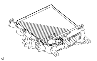
Attach the clamp.
-
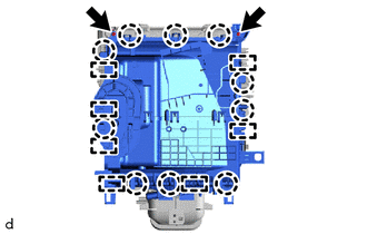
Attach the 8 guides and 10 claws to install the upper heater case.
-
Install the 2 screws.
-
-
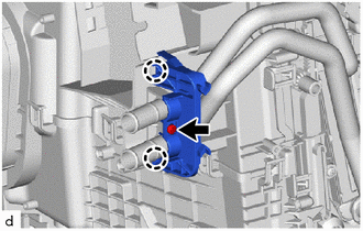
INSTALL COOLER EXPANSION VALVE
-
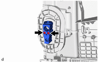
Install the cooler expansion valve.
-
Using a 4 mm hexagon wrench, install the cooler expansion valve with the 2 hexagon bolts.
- Torque:
- 3.5 N*m { 36 kgf*cm, 31 in.*lbf }
-
Install a new cooling unit packing.
-
-
INSTALL HEATER RADIATOR UNIT SUB-ASSEMBLY
-
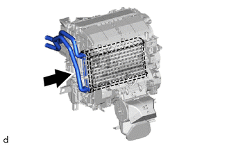
Install the heater radiator unit sub-assembly.
-
Attach the 2 claws to install the clamp.
-
Install the screw.
-
-
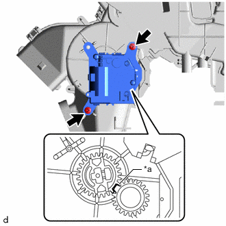
INSTALL NO. 2 AIR CONDITIONING RADIATOR DAMPER SERVO SUB-ASSEMBLY
-
*a Standard Position Align each No. 2 air conditioning radiator damper servo sub-assembly standard position.
-
Align each gear on the air conditioner radiator assembly side with the standard position as shown in the illustration.
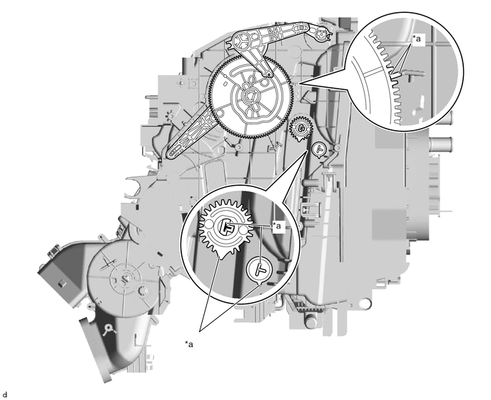
*a Standard Position - - -
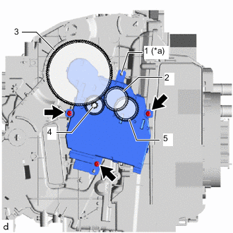
*a Positioning Rib Align the positioning rib and each gear in the order shown in the illustration and temporarily install the No. 2 air conditioning radiator damper servo sub-assembly.
-
Install the No. 2 air conditioning radiator damper servo sub-assembly with the 3 screws.
-
-
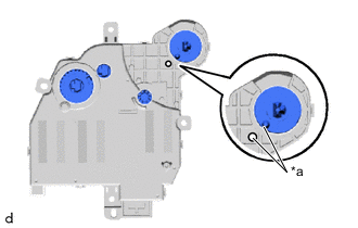
INSTALL NO. 1 AIR CONDITIONING RADIATOR DAMPER SERVO SUB-ASSEMBLY
-
*a Standard Position Align the gears with the standard position as shown in the illustration and temporarily install the No. 1 air conditioning radiator damper servo sub-assembly.
-
Install the No. 1 air conditioning radiator damper servo sub-assembly with the 2 screws.
-
-
INSTALL NO. 2 HEATER COVER (except Cold Area)
-
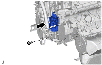
Install the No. 2 heater cover with the screw as shown in the illustration.
-
-
INSTALL QUICK HEATER ASSEMBLY (for Cold Area)
-
Install the quick heater assembly with the screw as shown in the illustration.
-
-
INSTALL HEATER COVER (for RHD)
-
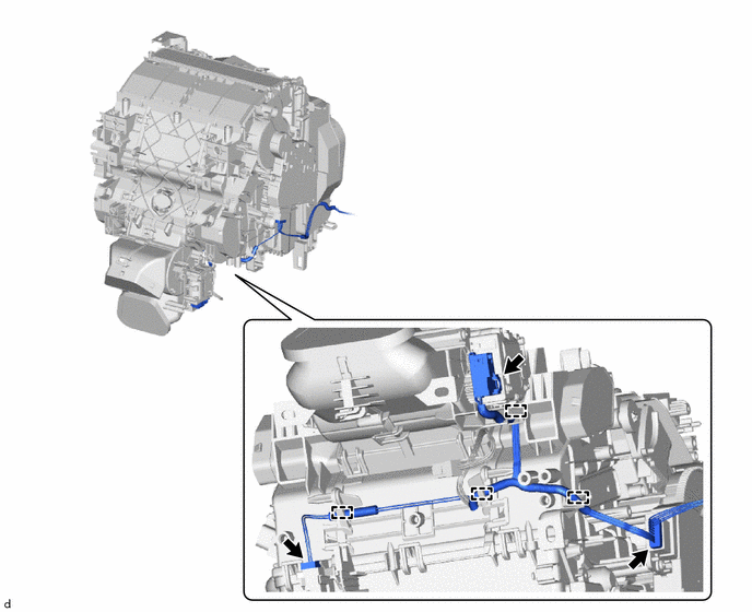
INSTALL AIR CONDITIONING HARNESS ASSEMBLY
-
Attach the 4 clamps to install the air conditioner harness assembly.
-
Connect the 2 connectors.
-
-
INSTALL DRAIN COOLER HOSE
-
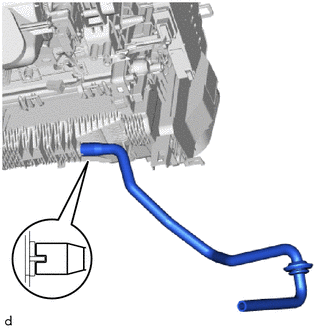
Align the protrusion on the lower heater case with the indentation on the drain cooler hose, and install the drain cooler hose.
-
-
INSTALL AIR CONDITIONING AMPLIFIER ASSEMBLY
-
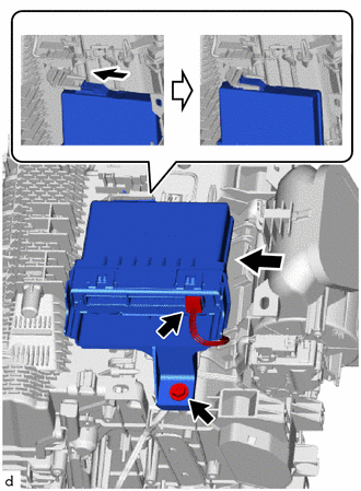
Insert the guide as shown in the illustration to temporarily install the air conditioning amplifier assembly.
Note
Make sure to align the protrusion on the air conditioning amplifier assembly with the indentation on the air conditioning unit assembly.
-
Install the air conditioning amplifier assembly with the screw.
-
Connect the air conditioning amplifier assembly connector.
-
-
INSTALL ASPIRATOR
-
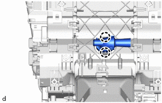
Attach the 2 claws to install the aspirator.
-
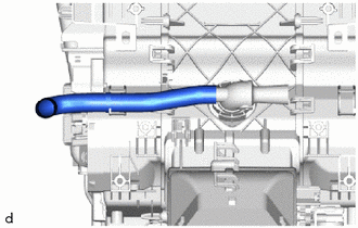
Install the aspirator hose.
-
-
INSTALL AIR CONDITIONING RADIATOR ASSEMBLY
-
Attach the 2 claws to install the air conditioning radiator assembly.
-
Install the 2 screws.
-
Attach the 3 clamps to install the air conditioning harness assembly.
-
Connect the No. 1 blower damper servo sub-assembly connector.
-