SEAT BELT WARNING SYSTEM(w/o Occupant Classification System) Rear Seat Belt Warning Light Malfunction
DESCRIPTION
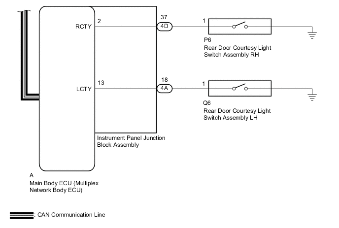
The main body ECU (multiplex network body ECU) detects whether either rear door is open or closed based on the condition of the left and right courtesy light switches and then sends the rear door status signal to the combination meter assembly. The combination meter assembly detects the rear seat belt state. The rear seat belt warning lights on the air conditioning control assembly illuminate or turn off in accordance with the rear door state, vehicle speed and rear seat belt state.
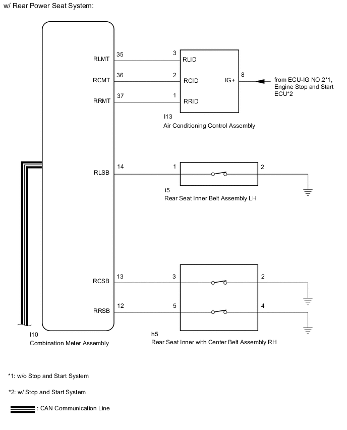
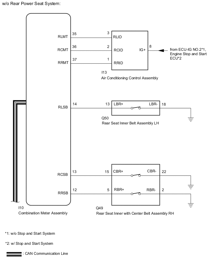
WIRING DIAGRAM
CAUTION / NOTICE / HINT
Note
-
The seat belt warning system uses the CAN communication system. First, confirm that there are no malfunctions in the CAN communication system. Refer to the How to Proceed with Troubleshooting procedure.
-
Inspect the fuses for circuits related to this system before performing the following procedure.
-
When replacing the combination meter assembly, make sure to replace it with a new one.
PROCEDURE
-
READ VALUE USING GTS (RR Door Courtesy SW, RL Door Courtesy SW)
-
Connect the GTS to the DLC3.
-
Turn the engine switch on (IG).
-
Turn the GTS on.
-
Enter the following menus: Body Electrical / Main Body / Data List.
-
Read the Data List according to the display on the GTS.
Body Electrical > Main Body > Data ListTester Display Measurement Item Range Normal Condition Diagnostic Note RR Door Courtesy SW Rear door courtesy light switch RH ON or OFF ON: Rear door RH open
OFF: Rear door RH closed
- RL Door Courtesy SW Rear door courtesy light switch LH ON or OFF ON: Rear door LH open
OFF: Rear door LH closed
-
Body Electrical > Main Body > Data ListTester Display RR Door Courtesy SW RL Door Courtesy SW OK The GTS display changes correctly in response to the rear door condition. Result Proceed to OK NG
NG 
GO TO LIGHTING SYSTEM Click here
OK 
-
-
READ VALUE USING GTS (2nd-Row Seatbelt Buckle [R], 2nd-Row Seatbelt Buckle [L], 2nd-Row Seatbelt Buckle [C])
-
Connect the GTS to the DLC3.
-
Turn the engine switch on (IG).
-
Turn the GTS on.
-
Enter the following menus: Body Electrical / Combination Meter / Data List.
-
Read the Data List according to the display on the GTS.
Body Electrical > Combination Meter > Data ListTester Display Measurement Item Range Normal Condition Diagnostic Note 2nd-Row Seatbelt Buckle (R) Rear seat belt buckle switch RH signal ON or OFF OFF: Rear RH seat belt fastened
ON: Rear RH seat belt unfastened
- 2nd-Row Seatbelt Buckle (L) Rear seat belt buckle switch LH signal ON or OFF OFF: Rear LH seat belt fastened
ON: Rear LH seat belt unfastened
- 2nd-Row Seatbelt Buckle (C) Rear seat center belt switch buckle signal ON or OFF OFF: Rear center seat belt fastened
ON: Rear center seat belt unfastened
-
Body Electrical > Combination Meter > Data ListTester Display 2nd-Row Seatbelt Buckle (R) 2nd-Row Seatbelt Buckle (L) 2nd-Row Seatbelt Buckle (C) Result Result Proceed to ON or OFF is displayed on the GTS screen according to the rear seat belt condition A ON or OFF is not displayed normally on the GTS screen according to the rear RH seat belt condition B ON or OFF is not displayed normally on the GTS screen according to the rear center seat belt condition ON or OFF is not displayed normally on the GTS screen according to the rear LH seat belt condition C
B 
INSPECT REAR SEAT INNER WITH CENTER BELT ASSEMBLY RH Click here
C
INSPECT REAR SEAT INNER BELT ASSEMBLY LH Click here
A
-
-
CHECK HARNESS AND CONNECTOR (AIR CONDITIONING CONTROL ASSEMBLY - BATTERY)
-
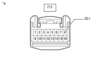
*a Front view wire harness connector
(to Air Conditioning Control Assembly)
Disconnect the air conditioning control assembly connector.
-
Measure the voltage according to the value(s) in the table below.
Standard Voltage Tester Connection Switch Condition Specified Condition I13-8 (IG+) - Body ground Engine switch on (IG) 11 to 14 V*1
10.5 to 16 V*2
Engine switch off Below 1 V
-
*1: w/o Stop and Start System
-
*2: w/ Stop and Start System
Result Proceed to OK NG -
NG
REPAIR OR REPLACE HARNESS OR CONNECTOR
OK
-
-
INSPECT AIR CONDITIONING CONTROL ASSEMBLY
-
Remove the air conditioning control assembly.
-
Inspect the air conditioning control assembly.
Result Proceed to OK NG
NG
REPLACE AIR CONDITIONING CONTROL ASSEMBLY Click here
OK
-
-
CHECK HARNESS AND CONNECTOR (AIR CONDITIONING CONTROL ASSEMBLY - COMBINATION METER ASSEMBLY)
-
Disconnect the I13 air conditioning control assembly connector.
-
Disconnect the I10 combination meter assembly connector.
-
Measure the resistance according to the value(s) in the table below.
Standard Resistance Tester Connection Condition Specified Condition I10-35 (RLMT) - I13-3 (RLID) Always Below 1 Ω I10-35 (RLMT) or I13-3 (RLID) - Body ground Always 10 kΩ or higher I10-36 (RCMT) - I13-2 (RCID) Always Below 1 Ω I10-36 (RCMT) or I13-2 (RCID) - Body ground Always 10 kΩ or higher I10-37 (RRMT) - I13-1 (RRID) Always Below 1 Ω I10-37 (RRMT) or I13-1 (RRID) - Body ground Always 10 kΩ or higher Result Proceed to OK NG
OK
REPLACE COMBINATION METER ASSEMBLY Click here
NG
REPAIR OR REPLACE HARNESS OR CONNECTOR
-
-
INSPECT REAR SEAT INNER WITH CENTER BELT ASSEMBLY RH
-
Remove the rear seat inner with center belt assembly RH.
-
Inspect the rear seat inner with center belt assembly RH.
Result Proceed to OK NG
NG
REPLACE REAR SEAT INNER WITH CENTER BELT ASSEMBLY RH Click here
OK
-
-
CHECK HARNESS AND CONNECTOR (REAR SEAT INNER WITH CENTER BELT ASSEMBLY RH - COMBINATION METER ASSEMBLY AND BODY GROUND)
-
Disconnect the h5*1 or Q49*2 rear seat inner with center belt assembly RH connector.
-
*1: w/ Rear Power Seat System
*2: w/o Rear Power Seat System
-
-
Disconnect the I10 combination meter assembly connector.
-
Measure the resistance according to the value(s) in the table below.
Standard Resistance w/ Rear Power Seat System Tester Connection Condition Specified Condition h5-3 - I10-13 (RCSB) Always Below 1 Ω h5-3 or I10-13 (RCSB) - Body ground Always 10 kΩ or higher h5-5 - I10-12 (RRSB) Always Below 1 Ω h5-5 or I10-12 (RRSB) - Body ground Always 10 kΩ or higher h5-4 - Body ground Always Below 1 Ω h5-2 - Body ground Always Below 1 Ω w/o Rear Power Seat System Tester Connection Condition Specified Condition Q49-15 (CBR+) - I10-13 (RCSB) Always Below 1 Ω Q49-15 (CBR+) or I10-13 (RCSB) - Body ground Always 10 kΩ or higher Q49-5 (RBR+) - I10-12 (RRSB) Always Below 1 Ω Q49-5 (RBR+) or I10-12 (RRSB) - Body ground Always 10 kΩ or higher Q49-22 (CBR-) - Body ground Always Below 1 Ω Q49-2 (RBR-) - Body ground Always Below 1 Ω Result Proceed to OK NG
OK
REPLACE COMBINATION METER ASSEMBLY Click here
NG
REPAIR OR REPLACE HARNESS OR CONNECTOR
-
-
INSPECT REAR SEAT INNER BELT ASSEMBLY LH
-
Remove the rear seat inner belt assembly LH.
-
Inspect the rear seat inner belt assembly LH.
Result Proceed to OK NG
NG
REPLACE REAR SEAT INNER BELT ASSEMBLY LH Click here
OK
-
-
CHECK HARNESS AND CONNECTOR (REAR SEAT INNER BELT ASSEMBLY LH - COMBINATION METER ASSEMBLY AND BODY GROUND)
-
Disconnect the i5*1 or Q50*2 rear seat inner belt assembly connector.
-
*1: w/ Rear Power Seat System
*2: w/o Rear Power Seat System
-
-
Disconnect the I10 combination meter assembly connector.
-
Measure the resistance according to the value(s) in the table below.
Standard Resistance w/ Rear Power Seat System Tester Connection Condition Specified Condition i5-1 - I10-14 (RLSB) Always Below 1 Ω i5-1 or I10-14 (RLSB) - Body ground Always 10 kΩ or higher i5-2 - Body ground Always Below 1 Ω w/o Rear Power Seat System Tester Connection Condition Specified Condition Q50-13 (LBR+) - I10-14 (RLSB) Always Below 1 Ω Q50-13 (LBR+) or I10-14 (RLSB) - Body ground Always 10 kΩ or higher Q50-18 (LBR-) - Body ground Always Below 1 Ω Result Proceed to OK NG
OK
REPLACE COMBINATION METER ASSEMBLY Click here
NG
REPAIR OR REPLACE HARNESS OR CONNECTOR
-